Release Notes
20G - Firmware versions and revisions can be found in the Versions tab above
Version 20.003 Signed (released 10/2024)
Catalog Number PowerFlex 755 (series B)
Features
This release includes the following system features.
Access to PowerFlex 750-Series Safe Speed Monitor Option Module Parameters in CIP Motion Mode
Feature First Identified as of PowerFlex 755 Series A Firmware Revision 16.003 and Series B Firmware Revision 20.003
This revision of firmware now supports access to the PowerFlex® 750-Series Safe Speed Monitor Option Module (catalog number 20-750-S1) parameters by using a human interface module (HIM) and Rockwell Automation® software applications (for example, Connected Components Workbench) when the drive is in CIP motion mode.
In previous firmware revisions, when a PowerFlex drive was in in CIP motion mode, the 20-750-S1 option module parameters were "read-only" and only accessible through the Ethernet browser. Per new security requirements, access via the Ethernet browser has been removed.
New Individual Output Phase Current Parameters Available
Feature First Identified as of PowerFlex 753 Firmware Revision 20.003
Feature First Identified as of PowerFlex 755 Firmware Revision 20.003
Parameters 990 [U Phase Curr], 991 [V Phase Curr], and 992 [W Phase Curr] have been added to the Monitor file and Metering group to provide the RMS current of the individual phases of the inverter.
|
No.
|
Display Name
Full Name Description |
Values
|
Read-Write
|
Data
Type
| |
|
990
|
U Phase Curr
U Phase Current Output current present through terminal T1 (U phase) of inverter. |
Units:
Default: Min/Max: |
Amps
0.0 0.0 / Rated Amps x 2 |
RO
|
Real
|
|
991
|
V Phase Curr
V Phase Current Output current present through terminal T2 (V phase) of inverter. |
Units:
Default: Min/Max: |
Amps
0.0 0.0 / Rated Amps x 2 |
RO
|
Real
|
|
992
|
W Phase Curr
W Phase Current Output current present through terminal T3 (W phase) of inverter. |
Units:
Default: Min/Max: |
Amps
0.0 0.0 / Rated Amps x 2 |
RO
|
Real
|
See the PowerFlex 750-Series AC Drives Programming Manual, publication 750-PM001, for more details.
Corrected Anomalies in This Release
This release corrects the following anomalies.
Highest Rating of a Frame Size Not Supported for a Drive Replacement in I/O Mode
Corrected Anomaly with PowerFlex 753 Firmware Series A Revision 16.003 and Series B Revision 20.003
Corrected Anomaly with PowerFlex 755 Firmware Series A Revision 16.003 and Series B Revision 20.003
Previously, I/O mode did not support replacing a lower drive rating with the highest drive rating (“top of frame”) of the same frame size. This firmware revision now allows you to replace a lower rated drive with the highest rated drive for the same frame size.
Hardware Over Current or Overspeed Limit Fault on Initial Start
Corrected Anomaly with PowerFlex 753 Firmware Revision 20.003
Corrected Anomaly with PowerFlex 755 Firmware Revision 20.003
When operating a PowerFlex® 753 or 755 drive in encoderless, interior permanent magnet (IPM) motor control mode and transitioning from “DC Brake” hold to “Running,” a Fault 12 “HW OverCurrent” or a Fault 25 “OverSpeed Limit” could occur on initial start. This firmware revision resolves this issue.
Encoder PPR Must be a Power of 2
Corrected Anomaly with PowerFlex 753 Firmware Revision 20.003
Corrected Anomaly with PowerFlex 755 Firmware Revision 20.003
In previous releases of firmware, the encoder pulses per revolution (PPR) value set in parameter 2 [Encoder PPR] of the Single Incremental Encoder Option Module, was required to be an exponential value (power) of 2 (512, 1024, 2048, 4096) when operating a PowerFlex® 753 or 755 drive. This is no longer a requirement of this firmware revision. The drive can now operate with an encoder PPR that is not an exponential value of 2.
Communication Loss Fault was Resettable if the Option Module Failed
Corrected Anomaly with PowerFlex 753 Series A Firmware Revision 16.003 and Series B Firmware Revision 20.003
Corrected Anomaly with PowerFlex 755 Series A Firmware Revision 16.003 and Series B Firmware Revision 20.003
When an option module failed and faulted a PowerFlex® 750-Series drive, the fault could be cleared, and the drive could be reset and restarted. With this firmware revision, when an option module communication loss fault occurs and the module is off-line, the fault cannot be reset.
PowerFlex 755 Drive in CIP Motion Mode Faults with 20-750-S and 20-750-S1 Safety Option Module
Corrected Anomaly with PowerFlex 755 Series A Firmware Revision 16.003 and Series B Firmware Revision 20.003
When using a PowerFlex® 755 drive with these conditions, the drive and axis would initially report a healthy connection, but after idling for a one to two minutes would issue a “GuardStopFault” continuously:
-
Firmware revision 14.xxx
-
CIP motion mode
-
Safe Torque Off Option Module (catalog number 20-750-S)
-
Safe Speed Monitor Option Module (catalog number 20-750-S1)
The drive did not fault but reported a “Stop” condition. This anomaly has been corrected in this firmware revision.
Erroneous Digital Input Configuration B Alarm
Corrected Anomaly with PowerFlex 753 Series A Firmware Revision 16.003 and Series B Firmware Revision 20.003
Corrected Anomaly with PowerFlex 755 Series A Firmware Revision 16.003 and Series B Firmware Revision 20.003
An erroneous digital input conflict alarm (157 “DigIn Cfg B”) would occur when parameters 162 [DI Fwd Reverse] and 163 [DI Run] were configured to command the reverse direction and run the drive with 2-wire control. This firmware revision corrects this anomaly.
Adjustable Voltage Command Not Limited by the Max Voltage
Corrected Anomaly with PowerFlex 753 Series A Firmware Revision 16.003 and Series B Firmware Revision 20.003
Corrected Anomaly with PowerFlex 755 Series A Firmware Revision 16.003 and Series B Firmware Revision 20.003
Parameter 1139 [Adj Vltg Command] was not limited by the value entered in Parameter 36 [Maximum Voltage]. This issue is corrected with this firmware revision.
Update from Earlier Firmware Revision to Revision 16.001 Causes Ethernet Error Fault
Corrected Anomaly with PowerFlex 755 Series A Firmware Revision 16.003 and Series B Firmware Revision 20.003
Updating a drive from an earlier firmware revision to firmware revision 16.001 could cause an issue and a Fault 926 “Ethernet Error.” This firmware revision resolves this issue.
Offline Default Vales of Parameters 278, 743, and 1682 are Incorrect
Corrected Anomaly with PowerFlex 755 Firmware Revision
16.003
Corrected Anomaly with PowerFlex 753 Firmware Revision
16.003
The offline value of Parameter 278 [Anlg Out0 DataHi] was
not included in the Config Block Upload, preventing updating the offline
default value of 1.00 correctly.
The offline value of Parameter 743 [Home Return Speed]
failed to upload when its value was set to match the motor nameplate’s Hertz
value.
The offline default of parameter 1682 [Purge Frequency] was
incorrect with a value of zero. This anomaly is corrected, and the offline
default value is now set to 5.00 Hz.
These issues are now corrected in this firmware revision.
PowerFlex 755 Drive CIP Motion Axis Does Not Reach Stopped State
Corrected Anomaly with PowerFlex 755 Series A Firmware Revision 16.003 and Series B Firmware Revision 20.003
A PowerFlex® 755 drive CIP motion axis remained in the stopping state, due to the velocity of the axis never reaching 1% of motor rated speed. A new CIP motion attribute (Attribute 617, 0x269) has been added for Coast Time Limit in seconds. This attribute provides access to the value that moves the axis to the stopped state.
Drive Sleep/Wake Mode Status Does Not Update to ‘Wake’ on HIM and in Software
Corrected Anomaly with PowerFlex 753 Firmware Revision 20.003
Corrected Anomaly with PowerFlex 755 Firmware Revision 20.003
The 'Sleep/Wake' mode status did not change to ‘Wake’ on the HIM or in Connected Components Workbench® software when the drive awakened from the sleep state. This firmware revision resolves this issue.
Fault Configuration Data Shift in Communication Option Module
Corrected Anomaly with PowerFlex 753 Firmware Revision 20.003
Corrected Anomaly with PowerFlex 755 Firmware Revision 20.003
A connected communication option module experienced a fault configuration data shift in parameters 38 through 54. This issue has been resolved with this firmware revision.
Speed Command Causes Negative Speed Reference
Corrected Anomaly with PowerFlex 753 Series A Firmware Revision 16.003 and Series B Firmware Revision 20.003
Corrected Anomaly with PowerFlex 755 Series A Firmware Revision 16.003 and Series B Firmware Revision 20.003
The issue with a speed command that created a negative speed reference number has been corrected with this firmware revision. The speed command is now checked for invalid float numbers.
PowerFlex 750-Series 600/690V AC Frame 7 Drive Issues Overtemperature Fault with Auxiliary Power Supply Option Module
Corrected Anomaly with PowerFlex 753 Series A Firmware Revision 16.003 and Series B Firmware Revision 20.003
Corrected Anomaly with PowerFlex 755 Series A Firmware Revision 16.003 and Series B Firmware Revision 20.003
When used with a PowerFlex® 750-Series 600/690V Frame 7 drive and 24V DC power is applied to an Auxiliary Power Supply option module (catalog number 20-750-APS), a heatsink overtemperature (8 “Heatsink OvrTemp”) or Transistor overtemperature (9 “Trnsistr OvrTemp”) fault can occur. This firmware revision corrects this anomaly.
Automatic Device Configuration Connection Error with Dual-port EtherNet/IP Option Module
Corrected Anomaly with PowerFlex 753 Series A Firmware Revision 16.003 and Series B Firmware Revision 20.003
Corrected Anomaly with PowerFlex 755 Series A Firmware Revision 16.003 and Series B Firmware Revision 20.003
This revision corrects a connection error that occurred when using Firmware Supervisor and/or Automatic Device Configuration (ADC). To implement support for this revision, download PowerFlex® 753 and 755 firmware revision 20.003 to Firmware Supervisor.
Compatible Module Option does not Work for PowerFlex 755 Drive when Firmware Major Revisions are Different
Corrected Anomaly with PowerFlex 755 Series A Firmware Revision 16.003 and Series B Firmware Revision 20.003
The Compatible Module electronic keying option did not work when connecting to a PowerFlex® 755 drive with firmware revision 16.002 via the Embedded EtherNet/IP™ port when the major revision number in the project did not match.
Examples:
|
Project Firmware Revision
|
Drive Firmware Revision
|
Connection
|
|
16.002
|
16.002
|
Accepted
|
|
14.005
|
16.002
|
Rejected
|
|
13.001
|
16.002
|
Rejected
|
|
13.001
|
14.005
|
Rejected
|
With this revision of firmware, Compatible Module electronic keying now works with different major firmware revisions.
Known Anomalies from Previous Releases
These anomalies are from previous releases but are still known in this release.
Known Anomaly First Identified as of PowerFlex 755 Drives Firmware Revision 3.004
Known Anomaly First Identified as of PowerFlex 753 Drives Firmware Revision 5.001
The HIM startup on the PowerFlex 755 drive includes a feedback device selection step. Depending on the option modules installed, that step may first ask the user to choose a port, then a parameter. In some situations, the list of ports incorrectly shows multiple copies of 'Port 0 - PowerFlex 755' followed by the feedback port/module.
The incorrect behavior happens only under the following conditions:
- It is the first time that startup feedback selection has been run since flashing the drive.
- The feedback module is a dual encoder or UFB and no other option modules are installed.
- A reset to defaults of the drive NVS parameters has not been performed since the drive was last flashed.
When the incorrect port list appears, it is still possible to successfully select the feedback module port by following one of these methods.
- Scroll past the multiple copies of Port 0 to reach the desired feedback module.
- Press the Esc soft key to back up one screen, then select Feedback and press the Enter soft key to display the port selection screen a second time. This time the correct list will be shown.
Known Anomaly First Identified as of PowerFlex 755 Drives Firmware Revision 8.001
Known Anomaly First Identified as of PowerFlex 753 Drives Firmware Revision 8.001
In an application with the use of a PowerFlex 755 or PowerFlex 753 along with the 20-750-ENETR dual port Ethernet/IP module, a persistent stop command may appear in some cases. The action of disconnecting the Ethernet cable from the 20-750-ENETR module, which will result in the drive stopping, may follow with a nuisance fault action. This fault action previously noted is persistent communication of stop commands.
Known Anomaly First Identified as of PowerFlex 755 Drives Firmware Revision 8.001
Known Anomaly First Identified as of PowerFlex 753 Drives Firmware Revision 8.001
In an application with the use of a PowerFlex 755 or PowerFlex 753 along with the 20-750-ENETR dual port Ethernet/IP module, in which a user attempts to save all parameters using DriveExplorer® in some causes the save execution does not complete. When attempting to execute the save all parameters in DriveExplorer the software tool enters an infinite loop and does not progress through the save in some instances. To exit the loop, press the cancel button and check if the text file has been saved.
Known Anomaly First Identified as of PowerFlex 755 Drive Firmware Revision 6.004
Known Anomaly First Identified as of PowerFlex 753 Drive Firmware Revision 6.004
When running in Flux Vector open loop mode for induction motor or Interior Permanent Magnet (IPM) motor mode, the drive may experience an F918 exception event when the motor accelerates through a 7 Hz operating frequency due to the simultaneous transition from a 2 to 4 KHz carrier frequency. This exception can be avoided by setting parameter 40 [Mtr Options Cfg] bit 9 – PWM FreqLock], which will keep the carrier frequency at 4 KHz.
Known Anomaly First Identified as of PowerFlex 755 Drive Firmware Revision 2.011
Known Anomaly First Identified as of PowerFlex 753 Drive Firmware Revision 7.001
You cannot change the level of current used during the direction test on a permanent magnet motor while in Integrated Motion on EtherNet/IP (CIP Motion) mode. It is set at 10%. If the system requires more than 10% to turn the motor, it will fail to perform the test.
Universal Feedback Board Module Does Not Annunciate Fault
Known Anomaly First Identified as of:
- PowerFlex 755 Drive Firmware Revision 12.001
- PowerFlex 753 Drive Firmware Revision 12.001
When the UFB is configured to use the SSI Full Digital Feedback Device, the UFB does not annunciate a fault when the SSI Full Digital is the signal is lost. For full details on possible workarounds to this anomaly, see Technical Support Knowledgebase Article #463171. To determine if this notice affects you and for additional information, please refer to Knowledgebase Document Number #745654.
Functional Changes
This release has the following functional changes from the previous release.
Functional Changes for PowerFlex 753 and 755 Firmware Revision 20.003 and Later
Functional Changes Identified as of PowerFlex 753 Firmware Revision 20.003
Functional Changes Identified as of PowerFlex 755 Firmware Revision 20.003
PowerFlex® 753 and 755 firmware revision 20.003 and later is compatible with all catalog number 20F and 20G drives with the series B main control circuit board catalog number SK-R1-MCB2-PF753 or SK-R1-MCB2-PF755 installed only. The renewal kit catalog number and series are contained on the kit package label and/or nameplate.
Series A main control boards with catalog numbers SK-R1-MCB1-PF753 or SK-R1-MCB1-PF755 are compatible with PowerFlex 753 and 755 firmware revisions 16.003 and earlier, only.
Firmware revision 20.003 and later is not compatible with PowerFlex 755 frame 8 and above drives.
Application Notes
This release has the following application notes.
Application Notes
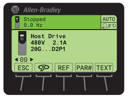
Use the Drive LCD HIM
- Access the Status screen, which is displayed on HIM power up.
- Use the
 or
or  key to scroll to Port 00 for the Host Drive.
 - Press the
 key to display its last-viewed folder.
 - Use the
 or
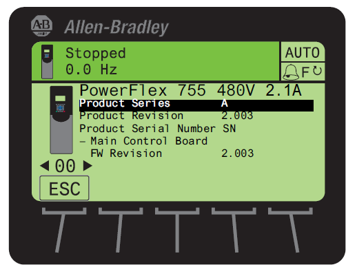
or  key to scroll to the DIAGNOSTIC folder.
 - Use the
 or
or  key to select Device Version.
 - Press the
 (Enter) key to display device version information.
FW Revision is listed under – Main Control Board.
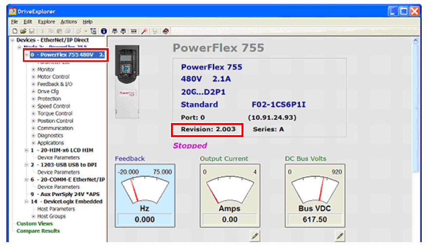
Use DriveExplorer Lite/Full
Important: You need DriveExplorer version 6.01 or later to interface with the PowerFlex 755 drive. To obtain the latest version, visit the Allen-Bradley Web Updates site located at http://www.ab.com/support/abdrives/webupdate
- Launch DriveExplorer and go online with the PowerFlex 755 drive. To connect to the drive, use a 1203-USB converter, a 1203-SSS converter, or an EtherNet/IP network connection.
- In the Devices hardware view, select the PowerFlex 755 drive.
Once selected, information regarding the PowerFlex 755 drive is shown in the right panel including the current firmware revision number.
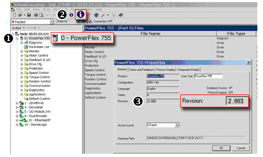
Use DriveExecutive
Important: You need DriveExecutive version 5.01 or later to interface with the PowerFlex 755 drive. To obtain the latest version, visit the Allen- Bradley Web Updates site located at http://www.ab.com/support/abdrives/webupdate
- Launch DriveExecutive and go online with the PowerFlex 755 drive. To connect to the drive, use a 1203-USB converter, a 1203-SSS converter, or an EtherNet/IP network connection.
- In the Drives hardware view, select the PowerFlex 755 drive (
 ).
). - Click the information icon (
 ) to display the drive’
s Properties dialog box.
) to display the drive’
s Properties dialog box.
In the Properties dialog box the “
Revision:”
field (![]() ) will show the drive
’s
current firmware revision number.
) will show the drive
’s
current firmware revision number.
Product Updates and Replacements
PowerFlex® 755 firmware revision 14.004 is installed by using a *.dmk file. Firmware updates for PowerFlex 755 drives can be performed using the following software:
|
Software
|
Version
|
Additional Software
|
Communication Adapters
|
|
ControlFLASH
Plus™
|
3.01.00
|
The following software
must be installed before
running ControlFLASH
Plus:
ControlFLASH Plus
version 2.00.00 or later
includes the installation
package for FactoryTalk
Linx.
|
One of the following
communication devices must
be used:
|
|
ControlFLASH™
|
15.03.00
|
One of the following
software packages must
be installed before
running ControlFLASH:
|
One of the following
communication devices must
be used:
|
Before You Begin a Firmware Update
If necessary, download and install the preferred software from the Product Compatibility and Download Center.
- ControlFLASH Firmware Upgrade Kit User Manual, publication 1756-UM105
- ControlFLASH Plus Quick Start Guide, publication CFP-QS001
For information on connecting the 1203-USB or 1203-SSS converter to your drive, see these publications:
- 1203-USB USB Converter User Manual, publication DRIVES-UM001
- 1203-SSS Smart Self-powered Serial Converter User Manual, publication 20COMM-UM001
Use ControlFLASH Plus to Update the Firmware
See “Use ControlFLASH Plus to update firmware” in the ControlFLASH Plus Quick Start Guide, publication CFP-QS001
Use ControlFLASH to Update the Firmware
Follow these steps to update your PowerFlex 755 drive firmware.
- Download firmware revision 14.004 from the Product Compatibility and Download Center.
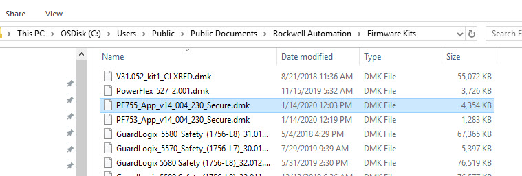
- Place the *.dmk file in one of the following directories on your computer:
- C:\Program Files (x86)\ControlFLASH
- C:\Users\Public\Documents\Rockwell Automation\Firmware Kit
- C:\Users\USER NAME\Downloads\RA
- C:\Users\USER NAME\Desktop\cfkits
Note: In this example, the file name is PF755_App_v14_004_230_Secure.dmk.
- Verify that the drive is stopped and not communicating with a controller, by inhibiting the drive in the software.
- Open ControlFLASH on your computer.
- In the Welcome dialog box, choose RSLinx Classic or FactoryTalk Linx. RSLinx Classic is used in this example.
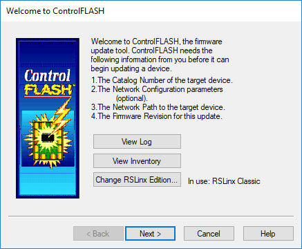
- Click Next.
- In the Catalog Number dialog box, select the appropriate drive family.
Important: Choose the appropriate “PowerFlex 755 xx” catalog number selection for your application. Do not choose an option that includes the “via…” option.

- Click Next.
- In the RSWho browser dialog box, select your drive.

- Click OK.
- In the Multiple Assemblies Found dialog box, select Port 0 – PowerFlex 755.

- Click OK.
- In the Firmware Revision dialog box, click Show all revisions.
- Below Revision, select 14.004.
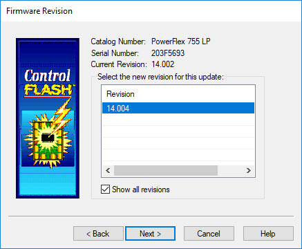
- Click Next.
- In the Summary dialog box, click Finish.
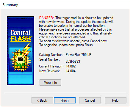
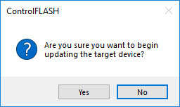
- In the ControlFLASH message box, click Yes.
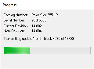
- The firmware update begins and a Progress dialog box appears.
- When the firmware update is complete, the Update Status dialog box appears.
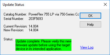
- Click OK.
- Exit ControlFLASH.
The drive firmware update has been completed.
Copyright © 2026 Rockwell Automation, Inc. All rights reserved.
Rockwell Automation, Allen-Bradley, and FactoryTalk are trademarks of Rockwell Automation, Inc.
To view a complete list of Rockwell Automation trademarks please click here.
Trademarks not belonging to Rockwell Automation are property of their respective companies.