
Release Notes
More information: PowerFlex® 525 Site
Version 5.001 (released 4/2016)
Catalog Number PowerFlex 525 (series A)
Features
This release includes the following system features.
New Flux Braking Function (LGX00131795 and LGX00172394)
System Feature Identified as of PowerFlex 525 Drives Firmware Revision 5.001
System Feature Identified as of PowerFlex 523 Drives Firmware Revision 3.001
Added a new Flux Braking function, and parameter A575 [Flux Braking EN] to enable/disable the function.
A575 [Flux Braking EN]
(With FRN 5.xxx and later.)
(With FRN 3.xxx and later.)
Enables/disables flux braking
|
Options
|
0 “Disable” (Default)
|
|
1 “Enable”
|
Added a new parameter d393 [Drive Status 2] that contains the drive status bit (Bit 1) for when the drive is performing the Flux Braking routine.
d393 [Drive Status 2]
(With FRN 5.xxx and later.)
(With FRN 3.xxx and later.)
Present operating conditions of the drive.
Where 1 = Condition True, 0 = Condition False
|
Bit 0 Jogging
|
|
Bit 1 Flux Braking
|
|
Bit 2 Motor Overload
|
|
Bit 3 Auto Restart Countdown
|
|
Bit 4 DC Braking
|
|
Bit 5 At Frequency
|
|
Bit 6 Auto Tuning
|
|
Bit 7 EM Braking
|
|
Bit 8 Current Limit
|
|
Bit 9 Reserved
|
|
Bit 10 Safety S1 (1)
|
|
Bit 11 Safety S2 (1)
|
|
Bit 12 F111 Status (1)
|
|
Bit 13 Safe Torque Permit (1)
|
|
Bit 14 Reserved
|
|
Bit 15 Reserved
|
(1) This bit status is specific to PowerFlex 525 drives only.
|
Values
|
Default:
|
Read Only
|
|
Min/Max:
|
00000 00000 00000 00000 / 11111 11111 11111 11111
| |
|
Display:
|
00000 00000 00000 00000
|
Drive status bit 1 is true when all the following conditions are true:
- A550 [Bus Reg Enable] = 1 “Enable”
- A575 [Flux Braking EN] = 1 “Enable”
- Decel ramp is active
New Parameter d393 [Drive Status 2] Added to Identify When Drive is Performing Autotune (LGX00136321 and LGX00174995)
System Feature Identified as of PowerFlex 525 Drives Firmware Revision 5.001
System Feature Identified as of PowerFlex 523 Drives Firmware Revision 3.001
Added a new parameter d393 [Drive Status 2] that contains the drive status bit (Bit 6) for when the drive is performing the Autotune routine.
d393 [Drive Status 2]
(With FRN 5.xxx and later.)
(With FRN 3.xxx and later.)
Displays the present operating conditions of the drive.
Where 1 = Condition True, 0 = Condition False
|
Bit 0 Jogging
|
|
Bit 1 Flux Braking
|
|
Bit 2 Motor Overload
|
|
Bit 3 Auto Restart Countdown
|
|
Bit 4 DC Braking
|
|
Bit 5 At Frequency
|
|
Bit 6 Auto Tuning
|
|
Bit 7 EM Braking
|
|
Bit 8 Current Limit
|
|
Bit 9 Reserved
|
|
Bit 10 Safety S1 (1)
|
|
Bit 11 Safety S2 (1)
|
|
Bit 12 F111 Status (1)
|
|
Bit 13 Safe Torque Permit (1)
|
|
Bit 14 Reserved
|
|
Bit 15 Reserved
|
(1) This bit status is specific to PowerFlex 525 drives only.
|
Values
|
Default:
|
Read Only
|
|
Min/Max:
|
00000 00000 00000 00000 / 11111 11111 11111 11111
| |
|
Display:
|
00000 00000 00000 00000
|
New Parameter d394 [Dig Out Status] Added to Store Status of Relay and Opto Outputs (LGX00137389)
System Feature Identified as of PowerFlex 525 Drive Firmware Revision 5.001
System Feature identified as of PowerFlex 523 Drive Firmware Revision 3.001
Added a new parameter d394 [Dig Out Status] that contains the digital output status of the Relay and Opto outputs.
d394 [Dig Out Status]
(With PowerFlex 525 FRN 5.xxx and later.)
(With PowerFlex 523 FRN 3.xxx and later.)
Displays relay output and opto output status.
|
Digit 1 Relay 1 Status
|
|
Digit 2 Relay 2 Status (1)
|
|
Digit 3 Opto 1 Status (1)
|
|
Digit 4 Opto 2 Status (1)
|
|
Digit 5 Not Used
|
(1) Setting is specific to PowerFlex 525 drives only.
|
Status
|
Bit Value = 0
|
Bit Value = 1
|
|
Relay 1 Status
(Normally Open) |
Not activated
(Relay 1 open) |
Activated
(Relay 1 closed) |
|
Relay 2 Status
(Normally Closed) |
Not activated
(Relay 2 closed) |
Activated
(Relay 2 open) |
|
Opto 1 Status
|
Not activated
|
Activated
|
|
Opto 2 Status
|
Not activated
|
Activated
|
New Option 31 Added to Digital Output Parameters to Indicate Auto-Restart Countdown (LGX00137490 and LGX00172402)
System Feature Identified as of PowerFlex 525 Drive Firmware Revision 5.001
System Feature identified as of PowerFlex 523 Drive Firmware Revision 3.001
Currently on the PowerFlex 520-series drive there is no visible indication to a local user that the drive is in an Auto-Restart countdown sequence, which automatically restarts the drive when the sequence is completed.
To enhance drive operation and provide the greatest level of safety, PowerFlex 525 Drive Firmware Revision 5.001 and PowerFlex 523 Drive Firmware Revision 3.001 include another digital output enum option (Option 31) which energizes the output if the drive is performing an Auto-Restart countdown sequence.
This output should only be energized when the drive is actually counting down to a pending re-start. If the drive faults on F033 (Auto Rstrt Tries), the output should not be active.
Option 31 “AutoRst Ctdn” is added to the following parameters:
- t069 [Opto Out1 Sel]
- t072 [Opto Out2 Sel]
- t076 [Relay Out1 Sel]
- t081 [Relay Out1 Sel]
Parameters t069, t072, and t081 are applicable to PowerFlex 525 drives only.
USB Applet Writes Configuration Code of the File into the Drive (LGX00147965 and LGX00174352)
System Feature Identified as of PowerFlex 525 Drives Firmware Revision 5.001
System Feature Identified as of PowerFlex 523 Drives Firmware Revision 3.001
The USB Applet now writes the drive type to the control module.
New Option 4 Added to Parameter P053 [Reset Defalts] to Power Cycle Drive (LGX00147966 and LGX00184867)
System Feature Identified as of PowerFlex 525 Drives Firmware Revision 5.001
System Feature Identified as of PowerFlex 523 Drives Firmware Revision 3.001
Added a new option 4 “Reset Module” to parameter P053 [Reset Defalts] to allow power cycling of the drive without having to remove and reapply mains power.
New Parameter d393 [Drive Status 2] Added to Indicate If Fault F111 (Safety Hardware) Occurred (LGX00152959)
System Feature Identified as of PowerFlex 525 Drive Firmware Revision 5.001
Added a new parameter d393 [Drive Status 2] that contains the drive status bit (Bit 12) that indicates if Fault F111 (Safety Hardware) has occurred.
d393 [Drive Status 2]
(With FRN 5.xxx and later.)
Present operating conditions of the drive.
Where 1 = Condition True, 0 = Condition False
|
Bit 0 Jogging
|
|
Bit 1 Flux Braking
|
|
Bit 2 Motor Overload
|
|
Bit 3 Auto Restart Countdown
|
|
Bit 4 DC Braking
|
|
Bit 5 At Frequency
|
|
Bit 6 Auto Tuning
|
|
Bit 7 EM Braking
|
|
Bit 8 Current Limit
|
|
Bit 9 Reserved
|
|
Bit 10 Safety S1
|
|
Bit 11 Safety S2
|
|
Bit 12 F111 Status
|
|
Bit 13 Safe Torque Permint
|
|
Bit 14 Reserved
|
|
Bit 15 Reserved
|
|
Values
|
Default:
|
Read Only
|
|
Min/Max:
|
00000 00000 00000 00000 / 11111 11111 11111 11111
| |
|
Display:
|
00000 00000 00000 00000
|
New Parameter t106 [SafetyFlt RstCfg] Added to Allow Fault F111 (Safety Hardware) Recovery without Power Cycling Drive (LGX00152960)
System Feature Identified as of PowerFlex 525 Drive Firmware Revision 5.001
Added a new parameter t106 [SafetyFlt RstCfg] that allows fault F111 (Safety Hardware) to be cleared without power cycling the drive when t106 is set to option 1 “FltClr Reset”.
New Option 30 Added to Digital Output Parameters to Indicate Safety Status (LGX00165031)
System Feature Identified as of PowerFlex 525 Drive Firmware Revision 5.001
Added a new digital output enum option (Option 30) to indicate the safety status.
Option 30 “SafeTqPermit” is added to the following parameters:
- t069 [Opto Out1 Sel]
- t072 [Opto Out2 Sel]
- t076 [Relay Out1 Sel]
- t081 [Relay Out1 Sel].
Option 31 = 1 when both S1 and S2 are closed.
|
S1
|
S2
|
Drive Fault
|
STO Status
|
Option 29
|
Option 30
|
|
0
|
0
|
None / F059 / F111
|
Safe Torque Off
|
1
|
0
|
|
0
|
1
|
F111
|
Safety Fault
|
0
|
0
|
|
1
|
0
|
F111
|
Safety Fault
|
0
|
0
|
|
1
|
1
|
None
|
Torque Permitted
|
0
|
1
|
|
1
|
1
|
F111
|
Safety Fault
|
0
|
0
|
Note: S1 and S2 are level sense signal, output shall not latch.
New Software Filter Added to Start Diagnostics (LGX00165033)
System Feature Identified as of PowerFlex 525 Drive Firmware Revision 5.001
Added a new software filter to the initial start failure detection routine to read the feedback twice.
New Permanent Magnet Motor Parameters
System Feature Identified as of PowerFlex 525 Drive Firmware Revision 5.001
A new option 4 “PM Control” is added to parameter P039 [Torque Perf Mode] to enable the use of PM motor control in PowerFlex 525 drives only.
P039 [Torque Perf Mode]
 Stop drive before changing this parameter.
Selects the motor control mode.
The PowerFlex 523 and PowerFlex 525 drives are capable of performing with the following motor control modes.
|
Options
|
0 “V/Hz”
|
|
1 “SVC” (Default)
| |
|
2 “Economize”
| |
|
3 “Vector”
| |
| 4 “PM Control” When P039 [Torque Perf Mode] is set to 4 and A535 [Motor Fdbk Type] is set to 0, 1, 2
or 3, the drive is in open loop PM motor control mode.
When P039 [Torque Perf Mode] is set to 4 and A535 [Motor Fdbk Type] is set to 4 or 5,
the drive is in closed loop PM motor control
mode.
|
The following parameters are added for use with PM motor control in PowerFlex 525 drives only.
A501 [PM IR Voltage]
 PowerFlex 525 only
(With FRN 5.xxx and later.)
Voltage across the stator resistance of the PM motor at the rated motor current displayed in line-to-line rms value.
|
Values
|
Default:
|
11.50V
|
|
Min/Max:
|
0.00V/655.35V
| |
|
Display:
|
0.01V
|
A502 [PM IXd Voltage]
 PowerFlex 525 only
(With FRN 5.xxx and later.)
Voltage across the d-axis stator inductance of the PM motor at the rated motor current and the rated motor frequency displayed in line-to-line rms value.
|
Values
|
Default:
|
17.91V
|
|
Min/Max:
|
0.00V/655.35V
| |
|
Display:
|
0.01V
|
A503 [PM IXq Voltage]
 PowerFlex 525 only
(With FRN 5.xxx and later.)
Voltage across the q-axis stator inductance of the PM motor at the rated motor current and the rated motor frequency displayed in line-to-line rms value.
|
Values
|
Default:
|
53.21V
|
|
Min/Max:
|
0.00V/655.35V
| |
|
Display:
|
0.01V
|
A504 [PM BEMF Voltage]
 PowerFlex 525 only
(With FRN 5.xxx and later.)
Back EMF.
|
Values
|
Default:
|
1640.0 Drive Rated Volts
|
|
Min/Max:
|
0.0/6000.0 Drive Rated Volts
| |
|
Display:
|
0.1V
|
A516 [PM Initial Sel]
 PowerFlex 525 only
(With FRN 5.xxx and later.)
PM initial angle detect.
|
Options
|
0 “Align” (Default)
|
|
1 “HFI” High Frequency Injection to detect initial angle.
| |
|
2 “Six Pulse”
|
A517 [PM DC Inject Cur]
 PowerFlex 525 only
(With FRN 5.xxx and later.)
Maximum DC current in amps applied to the motor in order to reset the rotor position of a PM motor.
|
Values
|
Default:
|
30%
|
|
Min/Max:
|
0/300%
| |
|
Display:
|
1%
|
A518 [PM Align Time]
 PowerFlex 525 only
(With FRN 5.xxx and later.)
Magnetic pole reorientation time.
|
Values
|
Default:
|
0.7 s
|
|
Min/Max:
|
0.0/60.0 s
| |
|
Display:
|
0.1 s
|
A519 [PM HFI NS Cur]
 PowerFlex 525 only
(With FRN 5.xxx and later.)
HFI NS Current to detect N/S Magnet.
|
Values
|
Default:
|
100%
|
|
Min/Max:
|
0/300%
| |
|
Display:
|
1%
|
A520 [PM Bus Reg Kd]
 PowerFlex 525 only
(With FRN 5.xxx and later.)
Derivative gain for bus regulator.
|
Values
|
Default:
|
2
|
|
Min/Max:
|
0/500
| |
|
Display:
|
1
|
A527 [PM FWKn 1 Kp]
 PowerFlex 525 only
(With FRN 5.xxx and later.)
The gain to ensure good performance in field weakening region.
|
Values
|
Default:
|
250%
|
|
Min/Max:
|
0/2000%
| |
|
Display:
|
1%
|
A528 [PM FWKn 2 Kp]
 PowerFlex 525 only
(With FRN 5.xxx and later.)
The gain to ensure robustness under step load in weakening region.
|
Values
|
Default:
|
100%
|
|
Min/Max:
|
0/8000%
| |
|
Display:
|
1%
|
A529 [PM Control Cfg]
 PowerFlex 525 only
(With FRN 5.xxx and later.)
Control Configuration for FFD (Feed Forward Decouple), MTPA (Maximum Torque Per Amp), and LDOB (Load Disturbance Observer).
 (Digit 1 starts from the right side of the word)
Where 1 = Condition True, 0 = Condition False
|
Digit 1 FFD Feed Forward Decouple
|
|
Digit 2 MTPA Maximum Torque Per Amp
|
|
Digit 3 LDOB Load Disturbance Observer
|
|
Digit 4 Not Used
|
|
Digit 5 Not Used
|
|
Values
|
Default:
|
00111
|
|
Min/Max:
|
00000/00111
| |
|
Display:
|
00000
|
A580 [Current Loop BW]
 PowerFlex 525 only
(With FRN 5.xxx and later.)
Current loop bandwidth (0 = Auto calculate the control gain of current loop).
|
Values
|
Default:
|
0 Hz
|
|
Min/Max:
|
0/65535 Hz
| |
|
Display:
|
1 Hz
|
A581 [PM Stable 1 Freq]
 PowerFlex 525 only
(With FRN 5.xxx and later.)
The start frequency for stabilization loop (P032 [Motor NP Hertz] x A581 [PM Stable 1 Freq]).
|
Values
|
Default:
|
0%
|
|
Min/Max:
|
0/100%
| |
|
Display:
|
1%
|
A582 [PM Stable 2 Freq]
 PowerFlex 525 only
(With FRN 5.xxx and later.)
Stabilization function will return to normal output after this frequency (P032 [Motor NP Hertz] x A582 [PM Stable 2 Freq]).
|
Values
|
Default:
|
45%
|
|
Min/Max:
|
0/100%
| |
|
Display:
|
1%
|
A583 [PM Stable 1 Kp]
 PowerFlex 525 only
(With FRN 5.xxx and later.)
Percentage of the gain A584 for stabilization loop.
|
Values
|
Default:
|
40%
|
|
Min/Max:
|
0/100%
| |
|
Display:
|
1%
|
A584 [PM Stable 2 Kp]
 PowerFlex 525 only
(With FRN 5.xxx and later.)
The gain for stabilization loop.
|
Values
|
Default:
|
250%
|
|
Min/Max:
|
0/2000%
| |
|
Display:
|
1%
|
A585 [PM Stable Brk Pt]
 PowerFlex 525 only
(With FRN 5.xxx and later.)
Percentage of rated power P037 [Motor NP Power] for the gain of (A584 [PM Stable 2 Kp] x A583 [PM Stable 1 Kp]).
|
Values
|
Default:
|
40%
|
|
Min/Max:
|
0/100%
| |
|
Display:
|
1%
|
A586 [PM Stepload Kp]
 PowerFlex 525 only
(With FRN 5.xxx and later.)
The gain to ensure robustness under step load in low speed region.
|
Values
|
Default:
|
0%
|
|
Min/Max:
|
0/1000%
| |
|
Display:
|
1%
|
A587 [PM 1 Efficiency]
 PowerFlex 525 only
(With FRN 5.xxx and later.)
Reduce full load current.
|
Values
|
Default:
|
120%
|
|
Min/Max:
|
0/2000%
| |
|
Display:
|
1%
|
A588 [PM 2 Efficiency]
 PowerFlex 525 only
(With FRN 5.xxx and later.)
Reduce no load current.
|
Values
|
Default:
|
500%
|
|
Min/Max:
|
0/2000%
| |
|
Display:
|
1%
|
A589 [PM Algor Sel]
 Stop drive before changing this parameter.
 PowerFlex 525 only
(With FRN 5.xxx and later.)
Selects the algorithm to use with your motor. Check with the manufacturer of your motor to determine whether it is an iPM or sPM motor.
|
Options
|
0 “Algorithm 1” (Default) Suggested for most motors.
|
|
1 “Algorithm 2” Enable an embedded algorithm to reduce oscillation in output waveform (use with
sPM motor only, do not enable for iPM motor)
|
Corrected Anomalies in This Release
This release corrects the following anomalies.
Inconsistent Abbreviations for Word Ethernet in Parameter Names (LGX00131460 and LGX174349)
Corrected: PowerFlex 525 Drives Firmware Revision 5.001
Corrected: PowerFlex 523 Drives Firmware Revision 3.001
The word “Ethernet” is not abbreviated consistently in parameter names.
Fast Accel or Decel Setting for 30 Hp Drive Causes Nuisance Fault (LGX00137447 and LGX00172396)
Corrected: PowerFlex 525 Drives Firmware Revision 5.001
Corrected: PowerFlex 523 Drives Firmware Revision 3.001
Known anomaly first identified as of PowerFlex 525 Drives Firmware Revision 1.001
Known anomaly first identified as of PowerFlex 523 Drives Firmware Revision 1.001
A 30 Hp drive will report a nuisance F013 (Ground Fault) fault when in SVC mode if a fast accel or decel time is set.
DC Injection Braking Does Not Work in VVC Mode with Encoder (LGX00137900)
Corrected: PowerFlex 525 Drives Firmware Revision 5.001
When performing DC Inject Braking in VVC Mode with an encoder, an F005 (OverVoltage) fault occurs.
VVC Mode without Encoder Loses Torque after Current Limit (LGX00137904)
Corrected: PowerFlex 525 Drives Firmware Revision 5.001
During speed-torque curves in VVC mode without an encoder, when the drive reaches maximum current and begins to fold back, the drive immediately loses control of the motor and torque drops to zero.
Fast Accel or Decel Times in VVC Mode without Encoder Causes Fault] (LGX00137915)
Corrected: PowerFlex 525 Drives Firmware Revision 5.001
During performance testing (accel/decel test) in VVC mode without an encoder, the drive will fault if the accel or decel time is set to 0.1 seconds and the load is at 100%.
Current Clamp Appears to Engage at ~165% Current in Some Conditions (LGX00138121 and LGX00172398)
Corrected: PowerFlex 525 Drives Firmware Revision 5.001
Corrected: PowerFlex 523 Drives Firmware Revision 3.001
Known anomaly first identified as of PowerFlex 525 Drives Firmware Revision 1.001
Known anomaly first identified as of PowerFlex 523 Drives Firmware Revision 1.001
Under some conditions the current clamp appears to engage at below 180% current. Current clamp now engages at proper level according to published specification.
HSDSI Stop Command Causes PowerFlex 525 Drive to not Fault on Idle I/O Connection (LGX00145750)
Corrected: PowerFlex 525 Drives Firmware Revision 5.001
Known anomaly first identified as of PowerFlex 525 Drives Firmware Revision 1.003
If the drive has a DeviceNet or EtherNet/IP I/O connection set up through an option card, when the I/O connection goes idle (such as PLC goes to program mode) the option card should cause the drive to report an F72 (Opt Net Loss) fault.
This does not happen when parameter P045 [Stop Mode] is set to 0 “Ramp, CF” (Default) and the I/O connection contains a continuous stop command (even when the drive has already stopped).
Output Phase Loss Timing is Not Well Defined (LGX00138245 and LGX00174403)
Corrected: PowerFlex 525 Drives Firmware Revision 5.001
Corrected: PowerFlex 523 Drives Firmware Revision 3.001
When parameter A557 [Out Ph Loss En] is set to 1 “Enable”, the drive will detect loss of output phase current in one or all of its output phases. This is usually caused by failure in the motor winding, cable or operation of switching device which interrupts motor current. It should be fast enough to detect current loss within a quarter cycle of the output frequency and yet resistance to false alarm cause by noise or interference. In any case, detection time shall not be more that one second. Loss of all three phase current should be detected during DC injection.
Also, parameter A576 [Phase Loss Level] is added to adjust the sensitivity of the output phase loss detection.
A576 [Phase Loss Level]
(With FRN 5.xxx and later.)
(With FRN 3.xxx and later.)
Output Phase Loss Level. Sets the threshold level which is used to determine an output phase loss condition.
Each motor phase must exceed this value. Decreasing this parameter's value lowers sensitivity.
|
Values
|
Default:
|
25% for Induction motor; 4.0% for PM motor
|
|
Min/Max:
|
0.0/100.0%
| |
|
Display:
|
0.1%
|
Italian Language Translation Issue for Datalink Parameter Names (LGX00138272)
Corrected: PowerFlex 525 Drives Firmware Revision 5.001
The names for Datalink parameters 153…160 are not properly translated in Italian language.
PowerFlex 525 Drive Always Returns the English Text "Parameters" for the File Name Attribute (LGX00138521)
Corrected: PowerFlex 525 Drives Firmware Revision 5.001
Known anomaly first identified as of Firmware Revision <rev?>
When retrieving the File Name attribute using the DPI Group and DPI International Group objects, the drive always returns the English text “Parameters” instead of the attribute in the current language setting.
Nuisance Trigger of Fault F029 (Analog In Loss) (LGX00147416)
Corrected: PowerFlex 525 Drives Firmware Revision 5.001
Known anomaly first identified as of PowerFlex 525 Drives Firmware Revision 2.002
A short timeout for comm loss detection causes nuisance triggering of fault F029 (Analog In Loss).
PowerFlex 525 Drives Intermittently Fault on F013 (Ground Fault) When Running at 415V (LGX00148203)
Corrected: PowerFlex 525 Drives Firmware Revision 5.001
Known anomaly first identified as of Firmware Revision 1.005
PowerFlex 525 Drives Intermittently Fault on F013 (Ground Fault) When Running at 415V.
Parameters F705 to F708 do not update when PowerFlex 525 Drive is in Single Drive Mode (LGX00148758 and LGX00149238)
Corrected: PowerFlex 525 Drives Firmware Revision 5.001
Known anomaly first identified as of PowerFlex 525 Drives Firmware Revision 1.005
The following parameters were not updating when PowerFlex 525 drive is in single drive mode.
- F705 [Drv 0 Logic Cmd]
- F706 [Drv 0 Reference]
- F707 [Drv 0 Logic Sts]
- F708 [Drv 0 Feedback]
The parameters now update in single drive mode.
Parameters F705 to F724 do not update when PowerFlex 525 Drive is in Multi-drive Mode (LGX00148760 and LGX00149239)
Corrected: PowerFlex 525 Drives Firmware Revision 5.001
Known anomaly first identified as of PowerFlex 525 Drives Firmware Revision 1.005
The following parameters were not updating when PowerFlex 525 drive is in multi-drive mode.
- F705 [Drv 0 Logic Cmd]
- F706 [Drv 0 Reference]
- F707 [Drv 0 Logic Sts]
- F708 [Drv 0 Feedback]
- F709 [Drv 1 Logic Cmd]
- F710 [Drv 1 Reference]
- F711 [Drv 1 Logic Sts]
- F712 [Drv 1 Feedback]
- F713 [Drv 2 Logic Cmd]
- F714 [Drv 2 Reference]
- F715 [Drv 2 Logic Sts]
- F716 [Drv 2 Feedback]
- F717 [Drv 3 Logic Cmd]
- F718 [Drv 3 Reference]
- F719 [Drv 3 Logic Sts]
- F720 [Drv 3 Feedback]
- F721 [Drv 4 Logic Cmd]
- F722 [Drv 4 Reference]
- F723 [Drv 4 Logic Sts]
- F724 [Drv 4 Feedback]
The parameters now update in multi-drive mode.
Power Cycle Needed to Restart Drive after F083 (EN Comm Loss) Fault (LGX00149075)
Corrected: PowerFlex 525 Drives Firmware Revision 5.001
Known anomaly first identified as of Firmware Revision 1.005
When a Stop Asserted command is sent by a Logix program to a PowerFlex 525 drive connected using the embedded Ethernet port and the Ethernet cable is removed, the drive faults on F083 (EN Comm Loss). After the fault is cleared, the drive cannot be restarted until it has been power cycled with the Ethernet cable disconnected.
PowerFlex 525 Drive Cycles between Active & Stopped with 2-wire Run and Comms Stop Asserted (LGX00149318)
Corrected: PowerFlex 525 Drives Firmware Revision 5.001
Known anomaly first identified as of PowerFlex 525 Drives Firmware Revision 1.005
The drive cycles between active and stop when the control source is set to digital input and the Stop Asserted command is issued through comms.
Wrong Bus Voltage Values Stored in Fault Volts Parameters (LGX00149508)
Corrected: PowerFlex 525 Drives Firmware Revision 5.001
Known anomaly first identified as of Firmware Revision 1.003
When the drive faults, the wrong bus voltage values are stored in parameters F651 to F660 [Fault X BusVolts].
Displayed Direction does not Update when Drive is Faulted (LGX00149525)
Corrected: PowerFlex 525 Drives Firmware Revision 5.001
When a fault occurs, the drive does not change displayed direction unless the fault is cleared.
Displayed direction now properly updates under faulted condition.
PowerFlex 525 Drive with Firmware Revision 2.002 on DeviceNet Network Faults after Power Cycling (LGX00151140)
Corrected: PowerFlex 525 Drives Firmware Revision 5.001
Known anomaly first identified as of Firmware Revision 2.002
When a drive with Firmware Revision 2.002 is connected to a DeviceNet network, power cycling the drive causes it to fault on F72 (Opt Net Loss).
Connecting a 1203-USB or 22-HIM-A3 Causes 25-COMM-E2P Card Port LED to Flash Red then Green (LGX00151435 and LGX00151438)
Corrected: PowerFlex 525 Drives Firmware Revision 5.001
Corrected: PowerFlex 523 Drives Firmware Revision 3.001
Known anomaly first identified as of PowerFlex 525 Drives Firmware Revision 2.002
Known anomaly first identified as of PowerFlex 523 Drives Firmware Revision 2.002
When a 1203-USB or 22-HIM-A3 is connected to a PowerFlex 520-series drive with a 25-COMM-E2P card attached, the Port LED on the 25-COMM-E2P card flashes red for a brief moment before flashing green and then turning solid green.
Parameter A548 [Power Loss Mode] Option 1 “Decel” does not work in Economizer Mode (LGX00151718, LGX00152017, and LGX00172399)
Corrected: PowerFlex 525 Drives Firmware Revision 5.001
Corrected: PowerFlex 523 Drives Firmware Revision 3.001
Known anomaly first identified as of PowerFlex 525 Drives Firmware Revision 2.002
Known anomaly first identified as of PowerFlex 523 Drives Firmware Revision 2.001
In Economizer mode, setting parameter A548 [Power Loss Mode] to option 1 “Decel” does not enable the inertia decel function when input power is cut off. The drive will exhibit the same behavior as when parameter A548 is set to option 0 “Coast”.
PowerFlex 525 Drive does not go into Position in Positioning Mode (LGX00152829)
Corrected: PowerFlex 525 Drives Firmware Revision 5.001
Known anomaly first identified as of PowerFlex 525 Drives Firmware Revision 2.002
In Positioning mode, PowerFlex 525 drives are unable to move to a specific position accurately when commanded using an absolute move.
PowerFlex 525 Drives Still Modulating in Sleep Mode (LGX00154020)
Corrected: PowerFlex 525 Drives Firmware Revision 5.001
Known anomaly first identified as of PowerFlex 525 Drives Firmware Revision 2.002
When the PowerFlex 525 drive goes into Sleep mode, is does not stop modulating but instead sends zero speed for the reference.
Duplicate IP Addresses Assigned When Powering Up Multiple PowerFlex 525 Drives response (LGX00155780)
Corrected: PowerFlex 525 Drives Firmware Revision 5.001
Known anomaly first identified as of PowerFlex 525 Drives Firmware Revision 2.002
Occasional duplicate IP addresses are assigned when powering up multiple PowerFlex 525 drives at the same time, using BOOTP and a Stratix switch with DHCP per port.
IP addresses are now properly checked to avoid duplication.
Incorrect Translation Text String for Parameter C122 [Cmd Stat Select] and A574 [RdyBit Mode Cfg] (LGX00155895 and LGX00172408)
Corrected: PowerFlex 525 Drives Firmware Revision 5.001
Corrected: PowerFlex 523 Drives Firmware Revision 3.001
Known anomaly first identified as of PowerFlex 525 Drives Firmware Revision 3.001
Known anomaly first identified as of PowerFlex 523 Drives Firmware Revision 2.001
Translated text string for Parameter C122 [Cmd Stat Select] (Polish only) and A574 [RdyBit Mode Cfg] (Spanish only).
Option 4 “Motor Overld” for Parameters t076 [Relay Out1 Sel] and t081 [Relay Out2 Sel] does not Function (LGX00159562)
Corrected: PowerFlex 525 Drives Firmware Revision 5.001
Known anomaly first identified as of PowerFlex 525 Drives Firmware Revision 4.001
A motor overload condition does not cause the normally open relay to change states even though parameters t076 [Relay Out1 Sel] or t081 [Relay Out2 Sel] is set to option 4 “Motor Overld”.
Relay output for motor overload option now functions as intended.
Default Text of Custom Group is not Translated (LGX00161117 and LGX00174360)
Corrected: PowerFlex 525 Drives Firmware Revision 5.001
Corrected: PowerFlex 523 Drives Firmware Revision 3.001
Known anomaly first identified as of PowerFlex 525 Drives Firmware Revision 2.002
Known anomaly first identified as of PowerFlex 523 Drives Firmware Revision 2.002
The default text of Custom Group is not translated.
Insufficient Discrepancy Time for STO Inputs (LGX00165030)
Corrected: PowerFlex 525 Drives Firmware Revision 5.001
The current time allowed for an input discrepancy is 10 ms, which is not consistent with other Rockwell Automation products (such as Kinetix servo drives).
For PowerFlex 525 Drives Firmware Revision 5.001 the input discrepancy time is increased to 1000 ms.
Parameter A573 Mtr Options Cfg Jerk Select Bit Set to 0 “Disabled” Also Disables Current Limit (LGX00166853)
Corrected: PowerFlex 525 Drives Firmware Revision 5.001
Known anomaly first identified as of PowerFlex 525 Drives Firmware Revision 4.001
When the “Jerk Select” bit in parameter A573 [Mtr Options Cfg] is set to 0 “Disabled”, parameter A484 [Current Limit 1] does not work as intended.
Current limit now works as intended with “Jerk Select” disabled.
Motor Nameplate FLA is Affecting Output Frequency (LGX00166855 and LGX00172401)
Corrected: PowerFlex 525 Drives Firmware Revision 5.001
Corrected: PowerFlex 523 Drives Firmware Revision 3.001
Known anomaly first identified as of PowerFlex 525 Drives Firmware Revision 4.001
Known anomaly first identified as of PowerFlex 523 Drives Firmware Revision 2.002
If you change the Motor FLA parameter P034 [Motor NP FLA], the motor speed increases the frequency and affects the Slip frequency in parameter d375 [Slip Hz Meter].
Slip frequency now works as intended.
PowerFlex 525 drive does not go Active When Start Command is Given (LGX00171175)
Corrected: PowerFlex 525 Drives Firmware Revision 5.001
Known anomaly first identified as of PowerFlex 525 Drives Firmware Revision 4.001
In certain conditions, a PowerFlex 525 drive will miss a Start command and not go active.
The drive will no longer miss start commands.
Incorrect Display for Parameter A437 [DB Resistor Sel] (LGX00172270 and LGX00173151)
Corrected: PowerFlex 525 Drives Firmware Revision 5.001
Corrected: PowerFlex 523 Drives Firmware Revision 3.001
Known anomaly first identified as of PowerFlex 525 Drives Firmware Revision 4.001
Known anomaly first identified as of PowerFlex 523 Drives Firmware Revision 2.002
When using the drive keypad to access parameter A437 [DB Resistor Sel], incorrect option text was displayed.
Some of the errors include the following:
- Option 4 is displayed as “Devalide” instead of “4% DutyCycle”.
- Option 6 is displayed as “SAS protect” instead of “6% DutyCycle”.
- Option 50 is displayed as “Correcodr on” instead of “50% DutyCycle”.
The option text is now displayed correctly.
Creeping at Zero Speed in VVC Mode (LGX00172990)
Corrected: PowerFlex 525 Drives Firmware Revision 5.001
Known anomaly first identified as of PowerFlex 525 Drives Firmware Revision 4.001
When the PowerFlex 525 drive is in VVC mode, the motor will creep when started at a command speed of zero hertz.
VVC mode corrects creep with and without an encoder.
Motor Starts Unexpectedly After Closing Safety Inputs (LGX00174108)
Corrected: PowerFlex 525 Drives Firmware Revision 5.001
Known anomaly first identified as of PowerFlex 525 Drives Firmware Revision 4.001
After closing the S1+S2 safety inputs, the drive will immediately start without needing to toggle the Start command.
Wake-Sleep Mode May Damage IGBTs (LGX00174217 and LGX00174742)
Corrected: PowerFlex 525 Drives Firmware Revision 5.001
Corrected: PowerFlex 523 Drives Firmware Revision 3.001
Known anomaly first identified as of PowerFlex 525 Drives Firmware Revision 1.003
Known anomaly first identified as of PowerFlex 523 Drives Firmware Revision 1.001
When the drive is coming out of sleep mode, the drive will trip on fault F012 (HW OverCurrent) or F013 (Ground Fault), afterwards an unrecoverable fault F013 will occur.
This anomaly happens under the following conditions:
- Parameter t100 [Sleep-Wake Sel] is set to option 3 “Command Freq” and
- Parameters t101…t104 are left at their default values.
Nuisance faults no longer occur when the drive is coming out of sleep mode.
Nuisance Fault When Output Phase Loss Enabled (LGX00174252 and LGX00174363)
Corrected: PowerFlex 525 Drives Firmware Revision 5.001
Corrected: PowerFlex 523 Drives Firmware Revision 3.001
Known anomaly first identified as of PowerFlex 525 Drives Firmware Revision 4.001
Known anomaly first identified as of PowerFlex 523 Drives Firmware Revision 2.001
Nuisance fault on F021 (Output Ph Loss) when parameter A557 [Out Phas Loss En] is set to option 1 “Enabled” for PowerFlex 520-series drives Frame D and E.
Drive Thermal Overload Fault Prematurely When Parameter A554 [Drv Ambient Sel] set to 60C (LGX00174611 and LGX00175941)
Corrected: PowerFlex 525 Drives Firmware Revision 5.001
Corrected: PowerFlex 523 Drives Firmware Revision 3.001
Known anomaly first identified as of PowerFlex 525 Drives Firmware Revision 4.001
Known anomaly first identified as of PowerFlex 523 Drives Firmware Revision 2.002
When parameter A554 [Drv Ambient Sel] is set to option 2 “60C”, a drive thermal overload fault will occur prematurely.
Fault F013 (Ground Fault) Occurs When Fast Accelerating in VVC Mode (LGX00156580)
Corrected: PowerFlex 525 Drives Firmware Revision 5.001
Known anomaly first identified as of Firmware Revision 2.002
When fast accelerating in VVC mode, PowerFlex 525 drives will fault on F013 (Ground Fault).
Known Anomalies from Previous Releases
These anomalies are from previous releases but are still known in this release.
Security Vulnerability in PowerFlex 525 AC Drives with Embedded EtherNet/IP (152230)
Corrected Anomaly with PowerFlex® 525 Drives Firmware Revision 5.002
Known Anomaly First Identified as of PowerFlex 525 Drives Firmware Revision 1.003
Catalog Number: 25B
This product release remediates a security vulnerability in the firmware. This vulnerability may affect the availability of network communications to this product due to resource exhaustion and/or memory corruption. An affected product would require manual intervention to recover. For complete details on the vulnerability and recommended mitigations, refer to KnowledgeBase article 1082684.
Application Notes
This release has the following application notes.
Application Notes
Using Connected Components Workbench™ Software
- Launch the Connected Components Workbench software.
- Open the project for your PowerFlex 525 drive.
- On the main screen, click
 to go online.
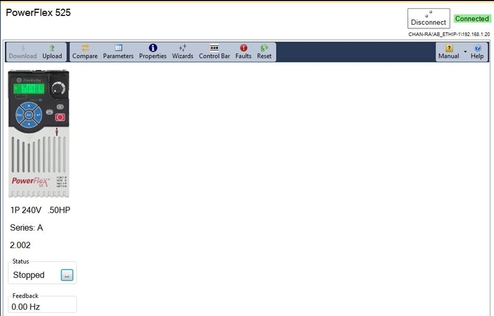
 The firmware revision is displayed on the screen as shown in this example.
Using Studio 5000 Logix Designer™ Software
- Launch the Logix Designer software.
- Open the project for your PowerFlex 525 drive.
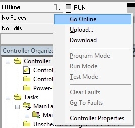
- On the main screen, click
 and select Go Online.
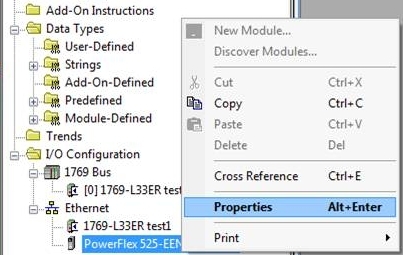
- Right-click on the PowerFlex 525 drive and select Properties.
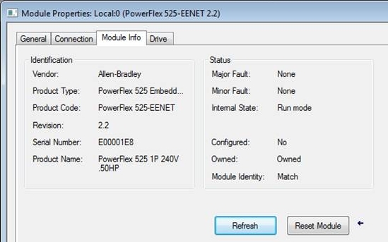
- In the Module Properties window, select the Module Info tab to display the firmware revision.


Using the Drive LCD Display and Keypad
|
Step
|
Key(s)
|
Example Display
| |
|
1.
|
When power is applied, the
last user-selected Basic
Display Group parameter
number is briefly displayed
with flashing characters. The
display then defaults to that
parameter’
s current value.
(Example shows the value of b001 [Output Freq] with the drive stopped.) |
|
 |
|
2.
|
Press Esc to display the
Basic Display Group
parameter number shown on
power-up. The parameter
number will flash.
|
 |
 |
|
3.
|
Press the Up Arrow or Down
Arrow to scroll to parameter
b029 [Control SW Ver].
|

or
 |
 |
|
4.
|
Press Enter to display the
drive’
s firmware revision.
|
 |
 |
Product Updates and Replacements
Using the USB Utility Application
- Separate the Control Module from the Power Module.
|
TIP
|
For more information on how to separate the Control Module from the
Power Module, see the PowerFlex® 520-Series Adjustable Frequency AC
Drive User Manual, publication 520-UM001.
|
- Connect one end of a USB cable to the USB port on the back of the Control Module.
- Connect the other end to the PC. A Windows® Explorer window appears.
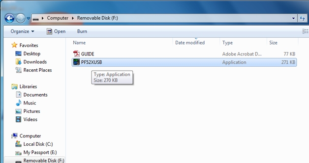
- Launch the PF52XUSB utility application. The PowerFlex 520-Series USB Application window appears.
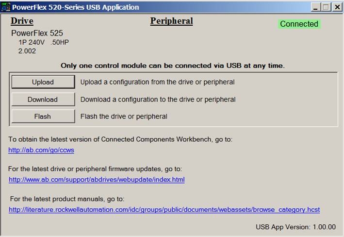
- Click Flash and select the firmware with which you want to update the module.
- Click Yes. The Confirm Flash Update dialog box appears. It displays the current firmware revision and the new revision to be flashed.
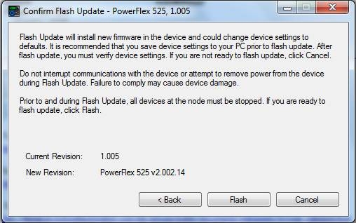
- Click Flash.
- When the process is complete, click OK.
- Close the application and disconnect the Control Module from the PC.
- Connect the Control Module to the Power Module and power cycle the drive.
- During the boot-up sequence, the following commands are displayed on the drive’ s LCD display: BOOT > COPY1 > COPY2 > ERASE > BOOT
- When fault F105 “C Connect Err” occurs, clear the fault to complete the flash update.
- The LCD display shows the drive data and current firmware revision.
Alternatively, you can verify the firmware revision by checking parameter b029 [Control SW Ver].
|
TIP
|
If the firmware revision did not update properly, you may need to reset the
drive to default and cycle drive power.
|
Using the ControlFLASH™ Software
- Install the flash kit utility for the PowerFlex 525 drive. You can download the flash kit utility from the Allen-Bradley Web Updates site at: http://www.ab.com/support/abdrives/webupdate/
- Launch the ControlFLASH software.
- On the ControlFLASH Welcome screen, click Next. The Catalog Number dialog box appears.
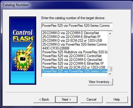
- Select the communication device you will use to update the firmware revision and click Next. For this example, select “PowerFlex 525 via PowerFlex 520-Series Comms” .
- In the Select Device to Update dialog box, expand the hardware view by clicking the “+” symbol next to the communication path you are using. For this example, click the “+” next to “AB_ETHIP-1, Ethernet ”.
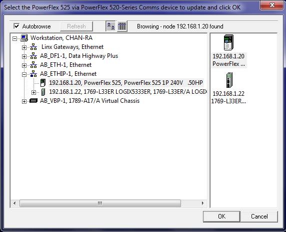
- Select the entry of the PowerFlex 525 drive you are updating and click OK. The Firmware Revision dialog box appears.
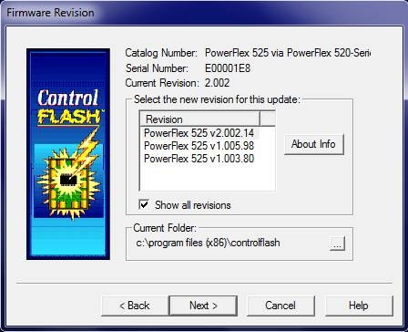
- Select the firmware revision you want to flash and click Next.
- Follow the remaining prompts to complete the flash update. When the process is complete, the new firmware revision is displayed in the dialog box.
Copyright © 2026 Rockwell Automation, Inc. All rights reserved.
Rockwell Automation, Allen-Bradley, and FactoryTalk are trademarks of Rockwell Automation, Inc.
To view a complete list of Rockwell Automation trademarks please click here.
Trademarks not belonging to Rockwell Automation are property of their respective companies.