Release Notes
CompactLogix L35E controller
Version 20.012 (released 6/2012)
Catalog Number 1769-L35E (series A)
Security
This release includes security enhancements as a part of our ongoing efforts to improve security. For information regarding Rockwell Automation's vulnerability disclosure process, please reference the Rockwell Automation Vulnerability Policy.
Access Denied dialog box does not appear when users without FactoryTalk Security access attempt to modify Motion Configuration (Lgx00184951)
Studio 5000 Logix Designer v29.00
Corrected Anomaly with Studio Logix Designer v30.00
When a user without Motion: Modify Configuration security credentials attempts to modify the motion configuration, an Access Denied dialog box does not appear.
Denial of Service/Buffer Overflow Vulnerability
Known Anomaly in Logix5000 Programmable Controllers, Firmware Revisions 16-21
A vulnerability exists in the Logix5000™ Programmable Controller product line that, if successfully exploited, can cause a Denial of Service ("DoS") or potentially allow an attacker to alter the operating state of the controller through a buffer overflow.
Risk Mitigations
Customers using affected controllers are encouraged to upgrade to an available firmware version that addresses the associated risk.
For details on affected controllers, recommended firmware revisions, and other risk mitigations, see Knowledgebase ID 970074.
Corrected
|
Cat. No.
|
Identified As Of
|
|
1769-L23E-QB1B,
1769-L23E-QBFC1B,
1769-L23-QBFC1B
|
Firmware Revision 20.012/RSLogix 5000
Software Version 20
|
|
1769-L31, 1769-L32C,
1769-L32E,1769-L35CR, 1769-L35E
|
Firmware Revision 20.012/RSLogix 5000
Software Version 20
|
|
1768-L43, 1768-L43S,
1768-L45, 1768-L45S
|
Firmware Revision 20.012/RSLogix 5000
Software Version 20
|
Safe State Values Does Not Work (00127022)
Known Anomaly
Safe State Values out does not work for 1794-IE4XOE2, 1794-OE12, and 1794-OE8H modules.
IMPORTANT: This is an RSLogix 5000 software anomaly that requires software version 20.01.00 for the correction.
Requirements
This release has the following requirements.
Firmware Requirements – 1769 CompactLogix Controllers
Catalog Numbers 1769-L31, 1769-L32C, 1769-L32E, 1769-L35CR, 1769-L35E
Consider the following before upgrading the firmware on your 1769 CompactLogix controller:
|
Consideration
|
Description
|
| Avoid Interrupting the
Firmware Upgrade
|
When upgrading your controller firmware, it is extremely
important to allow the upgrade to complete without
interruption.
If you interrupt the firmware upgrade either in the software or
by disturbing the physical media, you may render the
controller inoperable.
During an upgrade of the CompactLogix firmware, the
ControlFLASH™ utility displays various progress dialog
boxes. The progress dialog boxes contain these status
statements:
It is crucial that you do not interrupt the firmware upgrade
while these progress statements are displayed. Once the
Update Status dialog box indicates that the firmware upgrade
is complete, you may adjust your controller’s network
connection, make changes using controller-related software,
or cycle controller power.
|
|
End Cap Needed for
Firmware Upgrade
|
Attempting a firmware upgrade without the controller end cap
attached does not complete.
When upgrading your controller firmware, verify that your end
cap is properly attached and locked. If you attempt to upgrade
without the end cap attached, your firmware upgrade may not
complete successfully.
|
|
Controller Memory Limits
|
If your controller is close to its memory limit and this
firmware revision requires more project memory, you can
upgrade to a controller that has more memory.
|
|
Avoid Loss of
Communication During
Firmware Upgrade
|
Loss of communication or power during a controller firmware
upgrade may result in the controller’s rejection of the new
firmware. If the controller firmware upgrade fails due to those
conditions described, the following corrective actions may be
required.
|
|
Disconnect Controller from
DH-485 Network Before
Firmware Upgrade
|
If your controller is connected to a DH-485 network,
disconnect it from the DH-485 network before you update the
firmware of the controller. If you update the firmware of a
controller while it is connected to a DH-485 network,
communication on the network may stop.
|
| Firmware Upgrade on
1769-L32E or 1769-L35E
Controller
IMPORTANT: This
consideration applies only to
1769-L32E and 1769-L35E
controllers.
|
We recommend that you complete the following tasks before
attempting a firmware upgrade on a 1769-L32E or 1769-L35E:
IMPORTANT: If you cannot perform the tasks listed above
before attempting a controller firmware upgrade, Ethernet
traffic on the controller’s Ethernet port may cause the
ControlFLASH utility to timeout during the firmware upgrade. If
the timeout condition is not handled properly, you may render
the Ethernet port on the controller inoperable, requiring you to
return the controller to Rockwell Automation for repair.
In the event that a ControlFLASH timeout occurs, the software
displays an error dialog indicating that the ‘Target Device
failed to report the new revision number’, or that the upgrade
‘Failed to begin update to the target device’.
If the error dialog boxes display, check the MS status
indicator. If the indicator is flashing red, the upgrade is still in
progress and should not be interrupted. Do not cycle power to
the controller while the status indicator is flashing red.
If the upgrade completes, the controller power cycles itself and
indicates the upgrade is complete with a solid green MS status
indicator. The time required to complete the upgrade is
dependent on the level of Ethernet traffic.
If the controller does not complete the upgrade, the MS status
indicator continues flashing red. In this case, contact Rockwell
Automation Services and Support.
|
| Use of ControlFLASH
software, Version 9 (CPR9
SR3) with Firmware
Revision 19
IMPORTANT: This
consideration applies only
when you are using
firmware revision 19.
|
Consider the following before you install the ControlFLASH
software, version 9:
|
Corrected Anomalies in This Release
This release corrects the following anomalies.
Corrected
|
Cat. No.
|
Identified As Of
|
|
1769-L23E-QB1B,
1769-L23E-QBFC1B,
1769-L23-QBFC1B
|
Firmware Revision 20.012/RSLogix 5000
Software Version 20
|
|
1769-L31, 1769-L32C,
1769-L32E,1769-L35CR, 1769-L35E
|
Firmware Revision 20.012/RSLogix 5000
Software Version 20
|
|
1768-L43, 1768-L43S,
1768-L45, 1768-L45S
|
Firmware Revision 20.012/RSLogix 5000
Software Version 20
|
Outputs Remain On While Connection is Inhibited (00126406)
Known Anomaly
When inhibiting any connection that contains output data on the local CompactBus, under certain timing conditions, the outputs can stay on, even though the connection is inhibited.
Known Anomalies in This Release
This release has the following known anomalies.
Corrected: Logix Firmware/RSLogix 5000 Software 20.013
Browse the 1769 CompactBus (Lgx00117103, Lgx00129067)
Anomaly
Logix Firmware/RSLogix 5000 Software 20.012
Catalog Numbers 1769-L31, 1769-L32C, 1769-L32E, 1769-L35CR, 1769-L35E
- Browsing of the DeviceNet network will not occur.
- Browsing of the local 1769 CompactBus will not occur.
- Messages targeted to I/O modules on the local 1769 CompactBus will continuously error.
- Messages to devices on DeviceNet will continuously error.
- Power down the controller.
- Remove the battery.
- Let the controller set for approximately five minutes.
- Reconnect the battery.
- Redownload the application.
Applications with PowerFlex drives in the I/O configuration can experience a major non-recoverable fault (MNRF) (00200734, 00200735, 00200600, 00200599)
Corrected Anomaly as of Firmware Revision 31.011 and 30.014 for these catalog numbers:
- CompactLogix™ 5370 Controllers
- Compact GuardLogix® 5370 Controllers
Corrected Anomaly as of Firmware Revision 31.011 and 30.013 for these catalog numbers:
- ControlLogix® 5580 Controllers
- ControlLogix 5570 Controllers
- GuardLogix 5570 Controllers
Known Anomaly First Identified as of Firmware Revision 28.011 for these catalog numbers:
- ControlLogix 5580 Controllers
- CompactLogix 5380 Controllers
- Compact GuardLogix 5370 Controllers
Known Anomaly First Identified as of Firmware Revision 20.011 for these catalog numbers:
- ControlLogix 5570 Controllers
- GuardLogix 5570 Controllers
- ControlLogix 5570 (Redundancy) Controllers
- ControlLogix 5560 Controllers
- GuardLogix 5560 Controllers
- ControlLogix 5560 (Redundancy) Controllers
- CompactLogix 5370 Controllers
- 1769 CompactLogix Controllers
- 1768 CompactLogix Controllers
If a controller already has an application loaded into it that contains PowerFlex drives in the I/O configuration, a MNRF (Major Non-Recoverable Fault) can occur when any of the following occurs:
- A download of a project is performed to the controller.
- A PowerFlex drive is deleted while online.
- A firmware flash update of
the controller is performed.
For more information and workarounds, see Knowledgebase document 1067997.
Known Anomalies from Previous Releases
These anomalies are from previous releases but are still known in this release.
PI Function Block Appears to Stop Executing
Known Anomaly First Identified as of:
- Firmware Revision 16.024, 1768-L43, 1768-L45
- Firmware Revision 18.001, 1768-L43S, 1768-L45S
- Firmware Revision 18.011, 1769-L23-QBFC1B, 1769-L23E-QB1B,
1769-L23E-QBFC1B - Firmware Revision 16.022, 1769-L31, 1769-L32C, 1769-L32E, 1769-L35CR, 1769-L35E
The PI Function block appears to stop executing as the output does not change and instruction faults are logged.
If the PI instruction is being used in Linear mode, this floating point equation is used to calculate the ITerm.
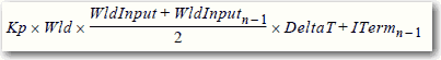
Due to the use of the single-precision floating point values, it is possible. This possibility is dependant on on the values of WLD and KP, for the ITerm value to be small enough, less than 0.0000001, to be lost when adding to the ITermn-1.
For more information regarding the PI instruction, see the Logix5000™ Controllers Process Control and Drives Instructions User Manual, publication 1756-RM006.
Alarm Systems Timeout Changes Require New Download (00069461)
Known Anomaly First Identified as of:
- Firmware Revision 16.024, 1768-L43, 1768-L45
- Firmware Revision 18.011, 1768-L43S, 1768-L45S
- Firmware Revision 18.011, 1769-L23-QBFC1B, 1769-L23E-QB1B, 1769-L23E-QBFC1B
- Firmware Revision 16.022, 1769-L31, 1769-L32C, 1769-L32E, 1769-L35CR, 1769-L35E
Changes made to the Buffer Timeout value for FactoryTalk® Alarm subscribers do not take effect until the existing buffer has been deleted.
The FactoryTalk alarm buffer (stored in Logix controller memory) is designed to persist through power cycles. If you change the Buffer Timeout value (via the Communication Setup dialog in FactoryTalk View SE), the controller does not use the new timeout value until the existing buffer is deleted and then recreated. To force recreation of this buffer, you can either:
- Redownload the project to the controller
- Disconnect the FactoryTalk Alarm subscriber and leave it disconnected until the existing timeout expires.
Cycle Power to Clear a Major Fault
Known Anomaly First Identified as of:
- Firmware Revision 17.005, 1769-L23E-QB1B, 1769-L23E-QBFC1B, 1769-L23-QBFC1B
- Firmware Revision 16.022, 1769-L31, 1769-L32C, 1769-L32E, 1769-L35CR, 1769-L35E
- Firmware Revision 16.024, 1768-L43, 1768-L45
- Firmware Revision 18.011, 1768-L43S, 1768-L45S
If a 1769 I/O fault occurs, you must cycle power to the CompactLogix™ controller after clearing the major fault. I/O communication is not restored until after the power cycle. Never use the fault handling routine to clear local I/O faults. Clear local I/O faults manually on a per case basis, and then the controller must be power cycled.
Time Synchronization Causes Controller to Become Local Master
Known Anomaly First Identified as of:
- Firmware Revision 18.011, 1769-L23E-QB1B, 1769-L23E-QBFC1B, 1769-L23-QBFC1B
- Firmware Revision 18.011, 1769-L31, 1769-L32C, 1769-L32E,1769-L35CR, 1769-L35E
- Firmware Revision 18.011, 1768-L43, 1768-L43S, 1768-L45, 1768-L45S
Enabling the time synchronization feature of a CompactLogix™ controller results in the controller becoming the local master. It does not result in the controller synchronizing with other wallclock times in the system.
Fault/Program States Not Supported by Using the Module Configuration
Dialog Box
Known Anomaly First Identified as of:
- Firmware Revision 17.005, 1769-L23E-QB1B, 1769-L23E-QBFC1B, 1769-L23-QBFC1B
- Firmware Revision 16.022, 1769-L31, 1769-L32E, 1769-L32C, 1769-L35E, 1769-L35CR
- Firmware Revision 16.024, 1768-L43, 1768-L45
- Firmware Revision 18.011, 1768-L43S, 1768-L45S
This anomaly applies to CompactLogix™ systems as follows:
- 1768 CompactLogix™ and 1769 CompactLogix controllers – Local I/O modules
- 1769 CompactLogix packaged controllers – Embedded I/O modules or local I/O modules, also known as expansion I/O modules in this case
In this description, the term I/O module refers to 1769 Compact output modules or output points on 1769 Compact combination modules.
RSLogix™ 5000 software does not support Fault/Program state action for I/O modules in CompactLogix systems. The controller cannot trigger the configured Fault/Program state action. You can configure the Fault/Program state action in RSLogix 5000 software, but the configuration does not take effect.
If either of the following conditions exists, outputs turn off, regardless of the Fault/Program state action configuration:
- The output loses communication with the controller.
- The controller is placed in Program mode.
Additionally, RSLogix 5000 software generates configuration tags for any I/O modules in the project. Some of the tags define configuration (C) data type members that include attributes for Fault/Program states, also known as alternate output states.
Because CompactLogix systems do not support Fault/Program state action for I/O modules, do not configure the attribute tags listed in the following table.
Attribute Tags to Avoid
|
Digital Output Modules
|
Analog Output Modules
|
|
Where CHx = the channel number
|
Corrected
|
Cat. No.
|
Corrected in the Following
|
|
1769-L23E-QB1B,
1769-L23E-QBFC1B,
1769-L23-QBFC1B
|
|
|
1769-L31,
1769-L32C,
1769-L32E,
1769-L35CR,
1769-L35E
|
|
Anomaly Browsing 1769 CompactBus (Lgx00135035, Lgx00129484)
Known Anomaly
|
Cat. No.
|
Identified As Of
|
|
1769-L23E-QB1B,
1769-L23E-QBFC1B,
1769-L23-QBFC1B
|
|
|
1769-L31,
1769-L32C,
1769-L32E,1769-L35CR, 1769-L35E
|
|
Your controller might experience an anomaly when browsing the 1769 CompactBus or through a 1769-SDN on the 1769 CompactBus. Signs of the anomaly are as follows.
- Browsing of the DeviceNet network will not occur.
- Browsing of the local 1769 CompactBus will not occur.
- Messages targeted to I/O modules on the local 1769 CompactBus will continuously error.
- Messages to devices on DeviceNet will continuously error.
Once the controller has entered this state, the only way to correct the anomalous behavior is to do the following.
- Power down the controller.
- Remove the battery.
- Let the controller set for approximately five minutes.
- Reconnect the battery.
- Redownload the application.
Corrected: Logix Firmware 20.014
Controller Logs Minor Fault Code 3 Type 93 (00129124, 00129117)
Known Anomaly
|
Cat. No.
|
Identified As Of
|
|
1769-L23E-QB1B,
1769-L23E-QBFC1B,
1769-L23-QBFC1B
|
Firmware Revision 20.011/RSLogix 5000
Software Version 20
|
|
1769-L31, 1769-L32C,
1769-L32E,1769-L35CR, 1769-L35E
|
Firmware Revision 20.011/RSLogix 5000
Software Version 20
|
Regardless of how you configure the RPIs for the I/O on the local CompactBus, the controller logs a minor fault Code 3 Type 93. If you clear this error, the fault will occur again in 35…40 minutes.
If this minor error is appearing more frequently, you have an application issue that needs to be corrected; for example, RPIs are set too fast, there are user tasks at or above priority 6, the controller is performing high-speed trending.
Using Automatic Device Configuration (00129165)
Known Anomaly First Identified as of:
- Firmware Revision 20.011, 1769-L23E-QB1B, 1769-L23E-QBFC1B, 1769-L23-QBFC1B
- Firmware Revision 20.011, 1769-L31, 1769-L32C, 1769-L32E,1769-L35CR, 1769-L35E
- Firmware Revision 20.011, 1768-L43, 1768-L43S, 1768-L45, 1768-L45S
When using the Automatic Device Configuration (ADC) feature, the Logix controller ‘owns’ the configuration in the drive. Do not use the HIM or other external tools, such as DriveExplorer™, to change drive parameters. Doing so can cause a sequence of events to occur that results in the connection between the controller and the drive to be dropped. Also, the controller cannot re-establish the connection.
Consider using the Write Mask function (drive Parameter 888 - [Write Mask Cfg]) to prevent tools that are connected to ports other than the Embedded EtherNet/IP port from writing to the drive.
ALMA and ALMD Tag Members Mismatch (00119996)
Known Anomaly First Identified as of:
- Firmware Revision 20.011, 1769-L23E-QB1B, 1769-L23E-QBFC1B, 1769-L23-QBFC1B
- Firmware Revision 20.011, 1769-L31, 1769-L32C, 1769-L32E,1769-L35CR, 1769-L35E
- Firmware Revision 20.011, 1768-L43, 1768-L43S, 1768-L45, 1768-L45S
The MinDurationPRE and MinDurationACC members of ALARM_ANALOG and ALARM_DIGITAL tags are defined as DINT (signed double integer) but they are treated as UDINT (unsigned double integer) by Logix firmware. This causes negative values of the tag members to be handled as large positive numbers when they must be handled as zero.
Accept Edits Effect on Controller Log (00122622)
Known Anomaly First Identified as of:
- Firmware Revision 20.011, 1769-L23E-QB1B, 1769-L23E-QBFC1B, 1769-L23-QBFC1B
- Firmware Revision 20.011, 1769-L31, 1769-L32C, 1769-L32E,1769-L35CR, 1769-L35E
- Firmware Revision 20.011, 1768-L43, 1768-L43S, 1768-L45, 1768-L45S
When you accept edits in LD, ST, and FBD, the controller will log an ‘Online Edit’ entry in the controller log. Accepting edits in an SFC routine is done by performing a partial import, resulting in a ‘Transaction Commit’ entry in the controller log.
This function is confusing because you can select to mask both entries separately. Selecting only Online edits would cause the Audit Value to change only when FBD, ST, and LD edits are made. SFC online edits would change the Audit Value only if the ‘Partial Import Online Transaction Completed’ bit was set.
Maximum Simultaneous Active Reconfigure Messages (00125204)
Known Anomaly First Identified as of:
- Firmware Revision 20.011, 1769-L23E-QB1B, 1769-L23E-QBFC1B, 1769-L23-QBFC1B
- Firmware Revision 20.011, 1769-L31, 1769-L32C, 1769-L32E,1769-L35CR, 1769-L35E
- Firmware Revision 20.011, 1768-L43, 1768-L43S, 1768-L45, 1768-L45S
The controller only supports three active reconfigure messages at a time. If more than three are triggered at a time, they complete (DN bit goes high), but not all modules are reconfigured.
For example, if you send five reconfiguration messages simultaneously, three reconfigure messages truly complete (DN bit goes high), and the I/O modules are reconfigured. The other two reconfigure messages indicate complete (DN bit goes high), but the I/O modules is not reconfigured. In this case, the last two are supposed to have errored (ER bit), but do not.
Corrected: Logix Firmware/Studio 5000 Software 21.011
Log On to FactoryTalk Dialog Box Displays When Launching RSLogix 5000 (00124955)
Known Anomaly First Identified as of:
- Firmware Revision 20.011, 1769-L23E-QB1B, 1769-L23E-QBFC1B, 1769-L23-QBFC1B
- Firmware Revision 20.011, 1769-L31, 1769-L32C, 1769-L32E,1769-L35CR, 1769-L35E
- Firmware Revision 20.011, 1768-L43, 1768-L43S, 1768-L45, 1768-L45S
When launching RSLogix™ 5000 software, the Log On to FactoryTalk® dialog box can display. This dialog box can be seen when you do not have Administrator privileges on the personal computer and the current user does not exist in the FactoryTalk directory. If this dialog box is canceled, the RSLogix 5000 software is not launched. When the dialog box is displayed, entering the credentials for a user that has Administrator privileges on the personal computer allows RSLogix 5000 software to be launched.
To avoid seeing this dialog box, you can add the current user or user group to the FactoryTalk directory. Follow these steps to add a user or user group to the FactoryTalk directory.
- Launch the FactoryTalk Administration Console (available from the Start menu).
- Select the Network directory when prompted.
(In some cases, to continue, you need to provide credentials for a user with Administrator privileges.)
- To allow access for a particular user, navigate to Network\System\Users and Groups\Users, right-click the Users folder and choose New>Windows Linked User.
- Click Add and provide the domain\logon name for the desired user.
(You can click Check Names to verify that the name was found.)
- To allow access for all authenticated users, navigate to Network\System\Users and Groups\User Groups, right-click the User Groups folder and choose New>Windows Linked User Group.
- Click Add and type the name of the user group, Authenticated Users.
The Log On to FactoryTalk dialog box can also be displayed when you are using Remote Desktop to connect to the personal computer running RSLogix 5000 software.
This dialog box appears because FactoryTalk Security does not recognize the computer name. To enable access through Remote Desktop for a specific computer, you must add the name of the computer initiating the Remote Desktop connection to the Network\System\Computers and Groups\Computers folder in the FactoryTalk Administration Console.
To allow all computers to connect, follow these steps.
- Open the FactoryTalk Administration Console and log in to the Network directory with your domain credentials.
- Navigate to Network\System\Security Policy. In the Computer Policy Settings section, set Identify terminal server clients with the name of to Server Computer.
IMPORTANT: If Use single sign-on is set to disable in FactoryTalk software, then the Log On to FactoryTalk dialog box is displayed each time RSLogix 5000 software is launched. When this is launched, proper user credentials must be entered to continue. (By default, ‘Use single sign-on’ is set to enable.)
SFC Action Body Executes Erroneously (00124697)
Known Anomaly First Identified as of:
- Firmware Revision 20.011, 1769-L23E-QB1B, 1769-L23E-QBFC1B, 1769-L23-QBFC1B
- Firmware Revision 20.011, 1769-L31, 1769-L32C, 1769-L32E,1769-L35CR, 1769-L35E
- Firmware Revision 20.011, 1768-L43, 1768-L43S, 1768-L45, 1768-L45S
In SFCs, when using time-limited actions in steps, if the program stays on a given step for greater than 24 days (2**32 ms) the accumulator of the timer (ACC) rolls over and the action body starts to execute again.
The time-limited action initializes its timer when it starts (step is first scanned). On subsequent scans, it compares the timers PRE and ACC value. If ACC<PRE, the action body executes. If ACC >=PRE, it is not executed. When the rollover occurs, the ACC,PRE, and the action body incorrectly exectutes.
Arithmetic State Flags (00122480)
Known Anomaly First Identified as of:
- Firmware Revision 20.011, 1769-L23E-QB1B, 1769-L23E-QBFC1B, 1769-L23-QBFC1B
- Firmware Revision 20.011, 1769-L31, 1769-L32C, 1769-L32E,1769-L35CR, 1769-L35E
- Firmware Revision 20.011, 1768-L43, 1768-L43S, 1768-L45, 1768-L45S
Arithmetic State flags anomalies.
- When dealing with floating point numbers, the controller does not truncate denormalized values or -0.0…0.0.
- For an integer divide, when the denominator is 0, the S:N and S:Z are not set.
- For the MOD instruction, the S:V is not set if an overflow occurred during the calculation.
Logix CPU Security Tool Unavailable
Known Anomaly First Identified as of:
- Firmware Revision 20.011, 1769-L23E-QB1B, 1769-L23E-QBFC1B, 1769-L23-QBFC1B
- Firmware Revision 20.011, 1769-L31, 1769-L32C, 1769-L32E,1769-L35CR, 1769-L35E
- Firmware Revision 20.011, 1768-L43, 1768-L43S, 1768-L45, 1768-L45S
The Logix CPU security tool does not work with version 20 controllers.
RSLogix 5000 Clock Update Does Not Support Some Operating Systems
Known Anomaly First Identified as of:
- Firmware Revision 20.011, 1769-L23E-QB1B, 1769-L23E-QBFC1B, 1769-L23-QBFC1B
- Firmware Revision 20.011, 1769-L31, 1769-L32C, 1769-L32E,1769-L35CR, 1769-L35E
- Firmware Revision 20.011, 1768-L43, 1768-L43S, 1768-L45, 1768-L45S
The RSLogix 5000 Clock Update tool does not support Windows 7 or Windows Server 2008 operating systems.
Tag Incorrectly Identified as Being on Scan (Lgx00148404)
Corrected as of:
- Firmware Revision 20.014, RSLogix™ 5000 Version 20.01
- Firmware Revision 24.011, Studio 5000 Logix Designer® 24.00
Known Anomaly First Identified as of:
- Firmware Revision 21.011, RSLogix 5000 Version 21.00
- Firmware Revision 23.012, Studio 5000 Logix Designer 23.00
Catalog Numbers:
- 1756 ControlLogix 5570
- 1756 GuardLogix® L7
- 5370 CompactLogix™ L1
- 5370 CompactLogix L2
- 5370 CompactLogix L3
- 1756 ControlLogix 5560 – Available with RSLogix 5000 Version 20 and earlier
- 1768 CompactLogix L4 – Available with RSLogix 5000 Version 20 and earlier
- 1769 CompactLogix L2 – Available with RSLogix 5000 Version 20 and earlier
- 1769 CompactLogix L3 – Available with RSLogix 5000 Version 20 and earlier
If you use RSLinx® Enterprise software for HMI communication and you try to modify or delete a controller tag online or try to modify an I/O module configuration, you can get the error 'Failed to modify properties. Tag is actively being read by one or more clients.' The controller improperly determines that a tag is on scan when it is not.
Functional Changes
This release has the following functional changes from the previous release.
V20 Additional Memory Requirements for 1769 CompactLogix Controllers
Functional Change
|
Cat. No.
|
Initial Firmware Revision/Software Version
|
|
1769-L31, 1769-L32C,
1769-L32E, 1769-L35CR,
1769-L35E
|
Firmware Revision 20.011/RSLogix 5000
Software Version 20
|
Firmware revision 20.000 or later may require more memory than previous revisions, for example, revision 10.xxx or 11.xxx). To estimate the additional memory that your project may require, use this table.
| If you
upgrade
from
revision
(add all
that
apply)
|
Then add the following memory requirements to your project
|
Which comes from this
type of memory
| |||
|
Component
|
Increase/Decrease
Per
Instance |
I/O
|
Data and
Logic
|
Safety
| |
|
19.x to
20.x
|
Task
|
+ 1312 bytes
|
|
ü
|
|
|
|
Program
|
+ 16 bytes
|
|
ü
|
|
|
|
Equipment Phase
|
+ 8bytes
|
|
ü
|
|
|
|
Routine
|
+ 24 bytes
|
|
ü
|
|
|
|
Add-On Instruction
|
+ 32 bytes
|
|
ü
|
|
|
|
Project with any tags that use
ALARM_ANALOG or ALARM_DIGITAL
data type
|
- 76 bytes
|
|
ü
|
|
|
|
Tag that uses ALARM_ANALOG data
type
|
+ 4 bytes
|
|
ü
|
|
|
|
Tag that uses ALARM_DIGITAL data
type
|
+ 24 bytes
|
|
ü
|
|
|
|
Tag that uses MOTION_GROUP data
type
|
+ 56 bytes
|
|
ü
|
|
|
|
Tag that uses COORDINATE_SYSTEM
data type
|
+ 940 bytes
|
|
ü
|
|
|
|
Tag that uses AXIS_CIP_DRIVE data
type
|
+ 676 bytes
|
|
ü
|
|
|
|
Tag that uses AXIS data type other than
AXIS_CIP_DRIVE
|
+672 bytes
|
|
ü
|
|
|
|
Standard Produced Tag
|
+ 4 bytes + (4 bytes x
number of
consumers)
|
ü
|
|
|
|
|
Standard Consumed Tag
|
+ 12 bytes
|
ü
|
|
|
|
|
Safety Produced Tag
|
+ 4 bytes
|
|
ü
|
|
|
|
Safety Consumed Tag
|
+ 4 bytes
|
|
ü
|
|
|
|
I/O Module
|
+ 8 bytes
|
|
ü
|
|
|
|
Module input connection
|
+ 4 bytes
|
|
ü
|
|
|
|
Module output connection
|
+ 4 bytes
|
|
ü
|
|
|
|
For each controller (> 1K bytes change):
|
|
|
|
|
|
|
1756-L6x
|
+ 1264 bytes
|
|
ü
|
|
|
|
1756-L6x
|
+ 1268 bytes
|
ü
|
|
|
|
|
1756-L6xS
|
+ 1264 bytes
|
|
ü
|
|
|
|
1756-L6xS
|
+1316 bytes
|
ü
|
|
|
|
|
1756-L6xS
|
+ 1312 bytes
|
|
|
ü
|
|
|
1756-L7x
|
+ 5588 bytes
|
|
ü
|
|
|
|
1756-L7x
|
+ 1296 bytes
|
ü
|
|
|
|
|
1768-L4x, 1768-L4xS
|
+1212 bytes
|
|
ü
|
|
|
|
1768-L4x
|
+ 1292 bytes
|
ü
|
|
|
|
|
1768-L4xS
|
+ 1340 bytes
|
ü
|
|
|
|
|
1768-L4xS
|
+ 1312 bytes
|
|
|
ü
|
|
|
1769-L23
|
+2488 bytes
|
ü
|
|
|
|
|
1769-L31
|
+2492 bytes
|
ü
|
|
|
|
|
1769-L32C, 1769-L35CR
|
+ 2812 bytes
|
ü
|
|
|
|
|
1769-L32E, 1769-L35E
|
+ 2496 bytes
|
ü
|
|
|
|
18.x to
19.x
|
|
<no change>
|
|
|
|
|
17.x to
18.x
|
Program
|
+ 8 bytes
|
|
ü
|
|
|
|
Equipment phase
|
+ 20 bytes
|
|
ü
|
|
|
|
Add-On Instruction
|
+ 12 bytes
|
|
ü
|
|
|
|
Each tag
In addition, if you use a tag of the types listed below, increase the memory as indicated for each instance: |
+ 4 bytes
|
|
ü
|
|
|
|
Produced tag
|
+ 36 bytes + (24
bytes x number of
consumers)
|
ü
|
|
|
|
|
Consumed tag
|
+ 24 bytes
|
ü
|
|
|
|
|
Data access control
|
+ 4 bytes per symbol
|
|
ü
|
|
|
|
Tag that uses ALARM_ANALOG data
type
|
- 20 bytes
|
|
ü
|
|
|
|
Tag that uses ALARM_DIGITAL data
type
|
+ 28 bytes
|
|
ü
|
|
|
|
Tag that uses MOTION_GROUP data
type
|
+ 76 bytes
|
|
ü
|
|
|
|
Tag that uses AXIS_SERVO_DRIVE or
AXIS_GENERIC_DRIVE data type
|
+ 786 bytes
|
|
ü
|
|
|
|
Tag that uses AXIS data type other than
AXIS_SERVO_DRIVE or
AXIS_GENERIC_DRIVE |
+ 818 bytes
|
|
ü
|
|
|
|
Tag that uses COORDINATE_SYSTEM
data type with no transform dimensions
|
+ 40 bytes
|
|
ü
|
|
|
|
Tag that uses COORDINATE_SYSTEM
data type with transform dimensions
|
+ 100 bytes
|
|
ü
|
|
|
|
Module input connection
|
+ 20 bytes
|
|
ü
|
|
|
|
Module output connection
|
+ 24 bytes
|
|
ü
|
|
|
|
Safety controller
|
- 8 bytes
|
|
ü
|
|
|
|
Safety partner
|
- 8 bytes
|
|
ü
|
|
|
|
For each controller (> 1K bytes change):
|
|
|
|
|
|
|
1756-L6x, 1756-L6xS, 1756-L63XT
|
+ 16728 bytes
|
|
ü
|
|
|
|
1768-L4x, 1768-L4xS
|
+ 14448 bytes
|
|
ü
|
|
|
|
1769-L2x
|
+ 35084 bytes
|
ü
|
|
|
|
|
1769-L31
|
+ 14740 bytes
|
ü
|
|
|
|
|
1769-L32C, 1769-L35CR
|
+ 35400 bytes
|
ü
|
|
|
|
|
1769-L32E, 1769-L35E
|
+ 35036 bytes
|
ü
|
|
|
|
|
1789-L10, 1789-L30, 1789-L60
|
+ 4992 bytes
|
ü
|
|
|
|
16.x to
17.x
|
Task
|
+ 4 bytes
|
|
ü
|
|
|
|
Program
|
+ 4 bytes
|
|
ü
|
|
|
|
Equipment phase
|
+ 8 bytes
|
|
ü
|
|
|
|
LD routine
|
+ 12 bytes
|
|
ü
|
|
|
|
FBD routine
|
- 8 bytes
|
|
ü
|
|
|
|
SFC routine
|
+ 28 bytes
|
|
ü
|
|
|
|
ST routine
|
+ 4 bytes
|
|
ü
|
|
|
|
Add-On Instruction
|
- 12 bytes
|
|
ü
|
|
|
|
If you use a tag of the types listed below,
increase the memory as indicated for
each instance:
|
|
|
|
|
|
|
Produced tag
|
+ [4 bytes + (4 bytes
x number of
consumers)
|
ü
|
|
|
|
|
Consumed tag
|
+ 8 bytes
|
ü
|
|
|
|
|
Tag that uses MESSAGE data type
|
+ 4 bytes
|
|
ü
|
|
|
|
Tag that uses ALARM_ANALOG data
type
|
- 64 bytes
|
|
ü
|
|
|
|
Tag that uses ALARM_DIGITAL data
type
|
- 28 bytes
|
|
ü
|
|
|
|
Tag that uses AXIS_SERVO_DRIVE or
AXIS_GENERIC_DRIVE data type
|
- 34 bytes
(2 bytes x number of output cam execution targets) |
|
ü
|
|
|
|
Tag that uses AXIS data type other than
AXIS_SERVO_DRIVE or
AXIS_GENERIC_DRIVE |
- 52 bytes
(2 bytes x number of output cam execution targets) |
|
ü
|
|
|
|
Tag that uses COORDINATE_SYSTEM
data type of 2 dimensions with 2
transform dimensions
|
+ 20 bytes
|
|
ü
|
|
|
|
Tag that uses COORDINATE_SYSTEM
data type of 3 dimensions with 3
transform dimensions
|
+ 108 bytes
|
|
ü
|
|
|
15.x to
16.x
|
If you use
a tag of
the types
listed
below,
increase
the
memory
as
indicated
for each
instance:
|
|
|
|
|
|
|
Tag that uses ALARM_ANALOG data
type (with no associated tag references)
|
+ 16 bytes
|
|
ü
|
|
|
|
Tag that uses ALARM_DIGITAL data
type (with no associated tag references)
|
+ 4 bytes
|
|
ü
|
|
|
|
Tag that uses ALARM_ANALOG data
type (if associated tags are configured
for the ALARM_ANALOG tag)
|
+ 22 bytes
+ (9 x the number of configured, associated tags) + (3 x the sum of the bytes used by the data type of each of the configured associated tags) For example, an analog alarm moved to V16.03 with two Associated Tags – one DINT (4 bytes) and one STRING (88 bytes) would need to add: 22 + 9(2) + 3(92) = 316 bytes |
|
ü
|
|
|
|
Tag that uses the
COORDINATE_SYSTEM data type
|
+ 132 bytes
|
|
ü
|
|
|
14.x to
15.x
|
Input
module
|
+ 4 bytes
|
ü
|
|
|
|
|
If you use a tag of the types listed below,
increase the memory as indicated for
each instance:
|
|
|
|
|
|
|
Produced tag
|
+ 12 bytes
|
ü
|
|
|
|
|
Consumed tag
|
+ 4 bytes
|
ü
|
|
|
|
|
Tag that uses COORDINATE_SYSTEM
data type
|
+ 748 bytes
|
|
ü
|
|
|
|
Tag the uses any AXIS data type
|
+ 800 bytes
|
|
ü
|
|
|
|
Task
|
+ 20 bytes
|
|
ü
|
|
|
|
Program or equipment phase
|
+ 24 bytes
|
|
ü
|
|
|
|
Routine
|
+ 4 bytes
|
|
ü
|
|
|
|
Serial port
|
+ 1120 bytes
|
|
ü
|
|
|
|
Project
|
+ 4012 bytes
|
|
ü
|
|
|
13.x to
14.x
|
If you use
a tag of
the types
listed
below,
increase
the
memory
as
indicated
for each
instance:
|
|
|
|
|
|
|
Tag that uses the COORDINATE
SYSTEM data type
|
+ 60 bytes
|
|
ü
|
|
|
|
Tag that uses any AXIS data type
|
+ 4 bytes
|
|
ü
|
|
|
12.x to
13.x
|
Program
|
+ 12 bytes
|
|
ü
|
|
|
|
Task
|
+ 4 bytes
|
|
ü
|
|
|
|
User-defined data type
|
+ 4 bytes
|
|
ü
|
|
|
|
I/O module
|
+ 16 bytes
|
ü
(8 bytes) |
ü
(8 bytes) |
|
|
|
If you use a tag of the types listed below,
increase the memory as indicated for
each instance:
|
|
|
|
|
|
|
Produced tag
|
+ 8 bytes
|
ü
|
|
|
|
|
Consumed tag
|
+ 8 bytes
|
ü
|
|
|
Copyright © 2026 Rockwell Automation, Inc. All rights reserved.
Rockwell Automation, Allen-Bradley, and FactoryTalk are trademarks of Rockwell Automation, Inc.
To view a complete list of Rockwell Automation trademarks please click here.
Trademarks not belonging to Rockwell Automation are property of their respective companies.