Release Notes
CompactLogix L43 and L45 Controller
Version 19.011 (released 9/2010)
Catalog Number 1768 CompactLogix Family (series A)
Security
This release includes security enhancements as a part of our ongoing efforts to improve security. For information regarding Rockwell Automation's vulnerability disclosure process, please reference the Rockwell Automation Vulnerability Policy.
Access Denied dialog box does not appear when users without FactoryTalk Security access attempt to modify Motion Configuration (Lgx00184951)
Studio 5000 Logix Designer v29.00
Corrected Anomaly with Studio Logix Designer v30.00
When a user without Motion: Modify Configuration security credentials attempts to modify the motion configuration, an Access Denied dialog box does not appear.
Denial of Service/Buffer Overflow Vulnerability
Known Anomaly in Logix5000 Programmable Controllers, Firmware Revisions 16-21
A vulnerability exists in the Logix5000™ Programmable Controller product line that, if successfully exploited, can cause a Denial of Service ("DoS") or potentially allow an attacker to alter the operating state of the controller through a buffer overflow.
Risk Mitigations
Customers using affected controllers are encouraged to upgrade to an available firmware version that addresses the associated risk.
For details on affected controllers, recommended firmware revisions, and other risk mitigations, see Knowledgebase ID 970074.
Requirements
This release has the following requirements.
Firmware Requirements – 1768 CompactLogix Controllers
Catalog Numbers 1768-L43, 1768-L43S, 1768-L45, 1768-L45S
Consider the following before a firmware upgrade on your 1768 CompactLogix™ controller.
|
Consideration
|
Description
|
| End cap needed for firmware
upgrade
|
When upgrading your controller firmware, verify that
your end cap is properly attached and locked. If you
attempt to upgrade without the end cap that is
attached, your firmware upgrade cannot complete
successfully.
|
|
Controller memory limits
|
If your controller is close to its memory limit and this
firmware revision requires more project memory, you
can upgrade to a controller that has more memory.
|
|
Avoid loss of communication
or power during firmware
update
|
Loss of communication or power during a controller
firmware upgrade can result in rejection of new
firmware by the controller. Loss of communication or
power during a controller firmware upgrade can result
in rejection of new firmware by the controller. If the
controller firmware upgrade fails due to such loss, take
the following corrective actions:
|
|
Disconnect controller from
DH-485 Network before
firmware upgrade
|
If your controller is connected to a DH-485 network,
disconnect it from the DH-485 network before you
upgrade the firmware of the controller. If you upgrade
the firmware of a controller while it is connected to a
DH-485 network, communication on the network can
stop.
|
| Use of ControlFLASH™
software, Version 9 (CPR9
SR3) with Firmware Revision
19
IMPORTANT: This
consideration applies only
when you are using firmware
revision 19.
|
Consider the following before you install the
ControlFLASH software, version 9:
If you click Cancel, you must select a
directory.
|
Your Controller Meets the
Following Conditions:
IMPORTANT: This
consideration applies only
when you are using firmware
revision 19.
|
Remove the CompactFlash card from the controller or
check the Load Image option of the CompactFlash
card. If it is set to On Power Up or On Corrupt Memory,
first store the project with the Load Image option set to
User Initiated.
Otherwise, you can get a major fault when you update
the firmware of the controller. This fault occurs
because the On Power Up or On Corrupt Memory
options cause the controller to load the project from
nonvolatile memory. The firmware mismatch after the
load then causes a major fault.
|
Features
This release includes the following system features.
DF1 Radio Modem Broadcast Support
System Feature First Identified as of:
- Firmware Revision 18.011, 1769-L23E-QB1B, 1769-L23E-QBFC1B, 1769-L23-QBFC1B
- Firmware Revision 18.011, 1769-L31, 1769-L32E, 1769-L32C, 1769-L35E, 1769-L35CR
- Firmware Revision 18.011, 1768-L43, 1768-L45, 1768-L43S, 1768-L45S
- Firmware Revision 16.022, 1756-L61, 1756-L61S, 1756-L62, 1756-L62S, 1756-L63, 1756-L63S, 1756-L63XT, 1756-L64, 1756-L65
DF1 Radio Modem support has been expanded to include broadcast capability. The DF1 Radio Modem functionality was initially provided with revision 16. With this expansion to include broadcast capabilities, you can configure a master or slave device to broadcast messages to all other stations in one instance.
Option to Suppress Array Faults During Postscan of SFC Actions
System Feature
|
Cat. No.
|
Available As Of
|
|
1769-L23E-QB1B,
1769-L23E-QBFC1B,
1769-L23-QBFC1B
|
Firmware Revision 19.011/RSLogix 5000 Software
Version 19
|
|
1769-L31, 1769-L32E,
1769-L32C, 1769-L35E,
1769-L35CR
|
Firmware Revision 19.011/RSLogix 5000 Software
Version 19
|
|
1768-L43, 1768-L45,
1768-L43S, 1768-L45S
|
Firmware Revision 19.011/RSLogix 5000 Software
Version 19
|
Option to Suppress Array Faults During Postscan of SFC Actions.
Use this feature to configure your application so that selected faults, that is, 4/20 and 4/83, encountered when an SFC action is postscanned, are suppressed.
When the fault is suppressed, the controller uses an internal fault handler to clear it. Clearing the fault causes the postscan process to skip the instruction containing the fault and continue with the next instruction.
This enhancement is valid only when SFC instructions are configured for automatic reset.
Safety Add-On Instructions
System Feature
|
Cat. No.
|
Available As Of
|
|
1768-L43, 1768-L45,
1768-L43S, 1768-L45S
|
Firmware Revision 18.011/RSLogix 5000 Software
Version 18
|
Add-On Instructions are now available for use within the safety task of GuardLogix and Compact GuardLogix controllers. Logic within a safety Add-On Instruction follows the same rules that apply to logic in safety routines with regard to instructions and tags that are permitted.
Safety Add-On Instructions can be SIL 3 certified with an approved certifying agency and reused without recertification as long as the signature of the safety Add-On Instruction is unchanged. Safety Add-On Instructions are included as part of the safety task signature, thus providing security of safety Add-On Instructions within a project.
For more information about using safety Add-On Instructions, see these publications:
- Logix5000 Controllers Add-On Instructions Programming Manual, publication 1756-PM010
- GuardLogix Controller Systems User Manual, publication 1756-RM093
Load Observer Available
System Feature First Identified as of:
- Firmware Revision 19.011, 1768-L43, 1768-L45, 1768-L43S, 1768-L45S
The Load Observer is a new servo loop feature that improves servo performance and robustness and simplifies system tuning.
Corrected Anomalies in This Release
This release corrects the following anomalies.
RSLinx External Access Options (Lgx00103263)
Known Anomaly First Identified as of:
- Firmware Revision 18.011, 1769-L23E-QB1B, 1769-L23E-QBFC1B, 1769-L23-QBFC1B
- Firmware Revision 18.011, 1769-L31, 1769-L32C, 1769-L32E,1769-L35CR, 1769-L35E
- Firmware Revision 18.011, 1768-L43, 1768-L43S, 1768-L45, 1768-L45S
Use RSLinx® Classic software, version 2.56, and RSLinx® Enterprise software, version 5.21 and later, for best results with the new External Access tag attributes provided with RSLogix 5000 software, version 18 and later, and controller firmware revision 18.011 and later.
If you use earlier versions of RSLinx Classic and RSLinx Enterprise software can result in anomalous behavior from the data servers with the External Access options Read Only and None.
For more information about tag data access attributes, see the Logix5000™ Controllers I/O and Tag Data Programming Manual, publication 1756-PM004.
Corrected
|
Cat. No. |
Corrected As Of |
|
1769-L23E-QB1B, 1769-L23E-QBFC1B |
Firmware Revision 19.011/RSLogix 5000 Software Version 19 |
|
1769-L31, 1769-L32C, 1769-L32E, 1769-L35CR, 1769-L35E |
Firmware Revision 19.011/RSLogix 5000 Software Version 19 |
|
1768-L43, 1768-L45, 1768-L43S, 1768-L45S |
Firmware Revision 19.011/RSLogix 5000 Software Version 19 |
Controller Fails Using Some MSG Instructions (Lgx00113381, Lgx00109216)
Controller may fail to transition from Run mode to Program mode when some MSG instruction types are used.
The failure to transition to Program mode occurs after the controller receives an 0x13 error code, that is, Configuration Data too Short. When a transition request is made after the controller receives an 0x13 error code, the controller acknowledges the request but never completes the transition.
Either of the following conditions cause this anomaly to occur:
• Controller executes SLC Typed Write message with the Number of Elements exceeding 108 bytes
• Controller executes SLC Typed Read message with the Number of Elements exceeding 118 bytes
The controller remains in Run mode until power is cycled.
Corrected
|
Cat. No. |
Corrected As Of |
|
1769-L23E-QB1B, 1769-L23E-QBFC1B |
Firmware Revision 19.011/RSLogix 5000 Software Version 19 |
|
1769-L31, 1769-L32C, 1769-L32E, 1769-L35CR, 1769-L35E |
Firmware Revision 19.011/RSLogix 5000 Software Version 19 |
|
1768-L43, 1768-L45, 1768-L43S, 1768-L45S |
Firmware Revision 19.011/RSLogix 5000 Software Version 19 |
Serial Port UART Stalls (Lgx00113379, Lgx00106893)
Serial port UART may stall during communication between a controller and a device.
This anomaly may have manifested itself in the following conditions when a controller is connected to another device, such as a PanelViewÔ terminal, through its serial port:
• Communication through the serial port stops completely.
• The controller’s RS-232 status indicator turns solid green.
Execute either of the following tasks to resume communication over the serial port connection:
• Cycle power to the controller.
• Change the serial port configuration, for example, the node number.
For more information about this anomaly, see the Technical Note titled Serial Port UART Appears To Be Stalling #67950, in the Technical Support
Knowledgebase available at http://www.rockwellautomation.com/knowledgebase/.
Corrected
|
Cat. No. |
Corrected As Of |
|
1769-L23E-QB1B, 1769-L23E-QBFC1B |
Firmware Revision 19.011/RSLogix 5000 Software Version 19 |
|
1769-L31, 1769-L32C, 1769-L32E, 1769-L35CR, 1769-L35E |
Firmware Revision 19.011/RSLogix 5000 Software Version 19 |
|
1768-L43, 1768-L45, 1768-L43S, 1768-L45S |
Firmware Revision 19.011/RSLogix 5000 Software Version 19 |
Copy File Instruction Results in Unexpected Execution (Lgx00114495, Lgx00114576)
The Copy File (COP) Synchronous Copy File (CPS) instruction use may result in Unexpected Execution.
If the COP or CPS instructions are configured so that the source and destination tags overlap, the instruction has unexpected execution.
For example, these graphics show an example COP instruction and its tag values before execution.


The result should be an array that contains all zeros. Instead, the result is an array that contains the values shown in this graphic.

Corrected
|
Cat. No.
|
Corrected As Of
|
|
1769-L23E-QB1B,
1769-L23E-QBFC1B
|
Firmware Revision 19.011/RSLogix
5000 Software Version 19
|
|
1769-L32E,
1769-L35E,
1769-L31,
1769-L32C,
1769-L35CR
|
Firmware Revision 19.011/RSLogix
5000 Software Version 19
|
|
1768-L43,
1768-L45,
1768-L43S,
1768-L45S
|
Firmware Revision 19.011/RSLogix
5000 Software Version 19
|
PCCC Command Bit (Lgx00113378, Lgx00111497)
PCCC command bit write does not update the controller.
When you use PCCC command bit write (CMD 0F FNC 02) to execute bit-level writes to a controller, the PCCC command appears to complete successfully but does not. Consequently, the data in the controller does not change in the targeted address in the memory. Instead, the write operation writes to the wrong address in memory; this may potentially cause a major non-recoverable fault.
A typical condition where you may be using this command is when you set up PLC/SLCÔ mapping in the controller that is the target of the communication. Additionally, you can use this command when communicating to a Logix controller from legacy systems that do not use the CIP protocol.
Logix controllers do not initiate this command.
For more information about this anomaly, see the Technical Note titled Bit writes fail with a Standard PanelView to a ControlLogixÒ processor with revision 18 firmware when using SLC/PLC mapping #69234, in the Technical Support Knowledgebase available at http://www.rockwellautomation.com/knowledgebase/.
Corrected
|
Cat. No.
|
Corrected As Of
|
|
1769-L23E-QB1B,
1769-L23E-QBFC1B
|
Firmware Revision 19.011/RSLogix
5000 Software Version 19
|
|
1769-L32E,
1769-L35E,
1769-L31,
1769-L32C,
1769-L35CR
|
Firmware Revision 19.011/RSLogix
5000 Software Version 19
|
|
1768-L43,
1768-L45,
1768-L43S,
1768-L45S
|
Firmware Revision 19.011/RSLogix
5000 Software Version 19
|
Watchdog Fault During Prescan Transition (Lgx00113376, Lgx00112413)
A watchdog fault occurs during prescan on a transition from Program mode to Run mode.
In large applications that include elements, such as many Add-On Instructions, Add-On Instructions with defined prescan routines, and complex Structural Text routines, the prescan could exceed 60 seconds. Because 60 seconds was the prescan watchdog setting, the controller experienced a major recoverable fault.
To correct this anomaly, the prescan watchdog has been changed to 300 seconds.
IMPORTANT: You cannot configure the prescan watchdog value.
Corrected
|
Cat. No.
|
Corrected As Of
|
|
1768-L43,
1768-L45,
1768-L43S,
1768-L45S
|
Firmware Revision 19.011/RSLogix
5000 Software Version 19
|
|
1769-L23E-QB1B,
1769-L23E-QBFC1B,
1769-L23-QBFC1B
|
Firmware Revision 19.011/RSLogix
5000 Software Version 19
|
|
1769-L31,
1769-L32C,
1769-L32E,
1769-L35CR,
1769-L35E
|
Firmware Revision 19.011/RSLogix
5000 Software Version 19
|
Partial Import Online Results in Major Non-recoverable Fault (Lgx00112034, Lgx00108203)
Controller experiences a major non-recoverable fault during a partial import online to a periodic or event task.
This anomaly occurred when the following conditions existed:
• Program in the Task previously had no Add-On Instructions, and the imported changes included Add-On Instructions.
• Program in the Task was being rescheduled under another Task.
Corrected
|
Cat. No.
|
Corrected As Of
|
|
1769-L23E-QB1B,
1769-L23E-QBFC1B,
1769-L23-QB1BFC
|
Firmware Revision 19.011/RSLogix 5000
Software Version 19
|
|
1769-L32E,
1769-L35E, 1769-L31,
1769-L32C,
1769-L35CR
|
Firmware Revision 19.011/RSLogix 5000
Software Version 19
|
|
1768-L43, 1768-L45,
1768-L43S, 1768-L45S
|
Firmware Revision 19.011/RSLogix 5000
Software Version 19
|
MCR Zones That Contain Add-On Instructions
When using Master Control Reset (MCR) zones that contain Add-On Instructions, the rungs may not evaluate correctly. After the Add-On Instruction, the remainder of the MCR zone is scanned as if the MCR zone were scanned true.
If your application requires the use of Add-On Instructions in MCR zones, we recommend you reposition the Add-On Instructions before or after the MCR zone and add their own conditional logic.
For more information about this anomaly, see the Technical Note titled MCR Zones Containing AOIs May Not Scan Rungs as False in Certain Firmware Revisions #68915, in the Technical Support Knowledgebase available at http://www.rockwellautomation.com/knowledgebase/.
Shutdown Fault Action Overrides the Drive State Change (00113377)
A Shutdown fault action that is issued by the controller overrides the drive state change only when the drive state change is reported as Disable.
Control Instructions May Experience Bump in Output Control Variable (00113391)
The Coordinated Control (CC), Internal Model Control (IMC), and Modular Multivariable Control (MMC) instructions can experience a bump in the output control variable (CV) if you transition from Manual mode to Auto mode soon after placing the controller into Run mode. For this anomaly to occur, your application must have one of the following conditions:
- CVxInitValue is not equal to zero.
- CVxProg is wired to a non-zero value that differs from CVxInitValue while in ProgramManual mode.
- CVxOper is wired to a non-zero value that differs from CVxInitValue while in OperatorManual mode.
In addition, the CC instruction can experience a bump in the output CV if you transition from Manual mode to Auto mode soon after a Modelinit. For this to occur, CVxEUMin and CVxEUMax must have a range other than 0…100.
In both cases, the bump occurs if the time from the initial condition to the Manual -> Auto mode switch is less than ((3 * CVxModelTC) + CVxModelDt).
The sooner the mode switch is made, the larger the bump.
Consumed Actual Position Not Tracking Consumed Commanded Position (00111591)
When a controller is configured for rotary operation and produces axes that other controllers consume, the consumed actual position was not tracking the consumed commanded position and manifested itself via two anomalous behaviors. The actual position appeared to have a small constant displacement in comparison to commanded position and would also exceed the expected unwind value.
IMPORTANT: This anomaly occurs only when the controller producing the axes is configured for rotary operation.
You could work around this anomaly in one of the following ways:
- If the produced axes were commanded axes, and it was acceptable in your application, you could reference the consumed axes’ Commanded Position.
- If the produced axes were virtual axes, you could reference the consumed axes’ Commanded Position. This option would work for all applications.
Motion Fault May Affect Fault Log or Cause Major Non-recoverable Fault (00113529)
If a Motion Group is configured as General Fault Type = Major Fault and a motion fault occurs, there is a remote possibility either the fault log gets overrun or a major non-recoverable fault occurs.
Controller Stops Processing Input Updates from Coarse Updates (00113524)
On the rare occasion that a controller misses an input update from a SERCOS motion module, the controller then stops processing input updates for 256 coarse updates. During the time in which the controller is not processing input updates, it uses data from the last input update before missing an update. Therefore, the controller does not use current input data for 256 coarse updates.
After 256 coarse updates, the controller resynchronizes with the SERCOS motion module and uses current data on the axis until another missed input update occurs.
Coordinate System May Experience Major Non-recoverable Fault (00108920)
The controller can experience a major non-recoverable (MNRF) fault if these conditions exist:
- System Configuration uses the following three coordinate systems:
- Coordinate system 1 (CS1) contains the X, Y, Z axes and is the Source Coordinate System for a Transform.
- Coordinate system 2 (CS2) contains the J1, J2, J3 axes and is the Target Coordinate System.
- Coordinate system 3 (CS3) contains the X, Y, A axes and is a third coordinate system that contains one or more axes in the coordinate system.
- Preconditions exist:
- A transform has been activated, that is, a Motion Coordinated Transform (MCT) instruction was executed, between the source, which is CS1, and target, which is CS2, coordinate systems.
- Any axis in CS2 is moving. For example, a Motion Axis Move (MAM) instruction is active on an axis in CS2, or a Motion Coordinated Linear Move (MCLM) instruction is active in CS2.
- Either of the following actions are taken:
- An MCLM or Motion Coordinated Circular Move (MCCM) instruction is executed on CS3.
- A MAM instruction is executed on any axis in CS1.
Motion Group Stop Instruction Does Not Disable Drive (00112392)
On a Velocity/Torque axis, an MGS instruction that is configured for a Stop mode of Fast Stop (including a programmed Stop mode of Fast Stop) decelerates the axis to a stop and then disables the drive. As of this release, the drive remains enabled.
Known Anomalies in This Release
This release has the following known anomalies.
S-curve Function Executes with Uninitialized Values
Corrected as of:
- Firmware Revision 20.011, 1769-L23E-QB1B, 1769-L23E-QBFC1B, 1769-L23-QBFC1B
- Firmware Revision 20.011, 1769-L31, 1769-L32C, 1769-L32E,1769-L35CR, 1769-L35E
- Firmware Revision 20.011, 1768-L43, 1768-L43S, 1768-L45, 1768-L45S
Known Anomaly First Identified as of:
- Firmware Revision 19.011, 1769-L23E-QB1B, 1769-L23E-QBFC1B, 1769-L23-QBFC1B
- Firmware Revision 19.011, 1769-L31, 1769-L32C, 1769-L32E,1769-L35CR, 1769-L35E
- Firmware Revision 19.011, 1768-L43, 1768-L43S, 1768-L45, 1768-L45S
When you perform a Partial Import Online (PIO) of a function block routine that contains S-curve function blocks across Logix platforms, set the Initialize bit in the backing tag control structure of all S-curve instructions. This configuration causes the S-curve instructions to reinitialize themselves.
Failure to set the Initialize bit in the backing tag control structure of all S-curve instructions, can cause the S-curve function block to execute with uninitialized values.
Corrected as of:
- Firmware Revision 20.011, 1769-L23E-QB1B, 1769-L23E-QBFC1B, 1769-L23-QBFC1B
- Firmware Revision 20.011, 1769-L31, 1769-L32C, 1769-L32E,1769-L35CR, 1769-L35E
- Firmware Revision 20.011, 1768-L43, 1768-L43S, 1768-L45, 1768-L45S
Corrected: SoftLogix™ 5800 Version 20.00.00
Known Anomaly First Identified as of:
- Firmware Revision 19.011, 1769-L23E-QB1B, 1769-L23E-QBFC1B, 1769-L23-QBFC1B
- Firmware Revision 19.011, 1769-L31, 1769-L32C, 1769-L32E,1769-L35CR, 1769-L35E
- Firmware Revision 19.015, 1768-L43, 1768-L43S, 1768-L45, 1768-L45S
When using Add-On Instructions, if you use the same backing/reference tag for multiple Add-On Instructions that are in different tasks, the controller can experience a major non-recoverable (MNRF) fault.
For example, you have an Add-On Instruction that is called MotorStart that is used twice in the application, once in Periodic Task 1 and once in Periodic Task 2. In both cases the MotorStart Add-On Instruction uses the same backing/reference tag PumpMotorStart.
The following events can occur when the program is executing:
1. Periodic Task 1 is executing and the Motor_Start is being scanned.
2. Periodic Task 2 pre-empts Periodic Task 1.
3. Periodic Task 2 runs and the Motor_Start is executed.
4. Periodic Task 1 is allowed to again execute and completes scanning of the Motor_Start.
5. Upon completion of scanning Motor_Start, the controller can MNRF.
The MNRF occurs if one instance of the Motor_Start scans false and the other scans true. To work around this anomaly, use individual backing/reference tag for all Add-On Instructions.
Corrected as of:
- Firmware Revision 20.011, 1768-L43, 1768-L43S, 1768-L45, 1768-L45S
Known Anomaly First Identified as of:
- Firmware Revision 19.011, 1768-L43, 1768-L43S, 1768-L45, 1768-L45S
With multiple rotations, multiple rotation angle is specified in the rotation matrix for an MCT or an MCTP instruction, the final rotated positions for the requested motion is not correct. The code originally rotated the axes in the following order: first around Z, then around Y, and finally around X. The order or rotation has been reversed. It now rotates the positions first around X, then around Y, and finally around Z.
Overshooting of an Motion Coordinated Linear Move (00135037)
Corrected as of:
- Firmware Revision 20.012, 1768-L43, 1768-L43S, 1768-L45, 1768-L45S
Known Anomaly First Identified as of:
- Firmware Revision 19.011, 1768-L43, 1768-L43S, 1768-L45, 1768-L45S
Overshooting of an MCLM instruction while using an MCCD instruction can occur. In an application, the AccOverrideFactor cannot be changed, but an open list of path segments is processed.
Corrected as of:
- Firmware Revision 20.011, 1768-L43, 1768-L43S, 1768-L45, 1768-L45S
Known Anomaly First Identified as of:
- Firmware Revision 19.011, 1768-L43, 1768-L43S, 1768-L45, 1768-L45S
Executing a Home Command (MAH) can cause unintended motion, equal to the negative unwind distance, when the controller executes the final offset move to the home position. The Conversion Constant and the Drive Resolution are the main contributors, along with being a rotary axis. Other parameter settings that contribute to this condition are as follows:
- Home Mode = Active
- Home Sequence = Marker or Switch-Marker
- Home Offset = Small incremental distance (that is, 5°)
- Rotary Configuration with an unwind
To solve, upgrade to firmware revision 20 of the ControlLogix® controller, or for versions before 20, set the Home Offset position to 0. Use a MAM instruction to move the offset distance, then use MRP (Motion Redefine Position) to the home position.
Master Axis Position Cam Instruction Does Not Execute As Expected (00113538)
Corrected as of:
- Firmware Revision 20.011, 1768-L43, 1768-L43S, 1768-L45, 1768-L45S
Known Anomaly First Identified as of:
- Firmware Revision 19.011, 1768-L43, 1768-L43S, 1768-L45, 1768-L45S
When a Master Axis Position Cam (MAPC) instruction, with Execution Schedule = Pending, is executed, its master axis is ignored. However, its master axis’ scaling constant is used to scale the Master Scaling parameter instead of the scaling constant on the axis that is active. Using the incorrect scaling constant results in incorrect overall scaling of the PCAM.
You can take one of the following actions to work around this anomaly:
- Set the PCAM’s master axis to be identical to the active master axis.
- Update the Master Scaling coefficient off the pending move to achieve desired scaling factor.
Known Anomalies from Previous Releases
These anomalies are from previous releases but are still known in this release.
PI Function Block Appears to Stop Executing
Known Anomaly First Identified as of:
- Firmware Revision 16.024, 1768-L43, 1768-L45
- Firmware Revision 18.001, 1768-L43S, 1768-L45S
- Firmware Revision 18.011, 1769-L23-QBFC1B, 1769-L23E-QB1B,
1769-L23E-QBFC1B - Firmware Revision 16.022, 1769-L31, 1769-L32C, 1769-L32E, 1769-L35CR, 1769-L35E
The PI Function block appears to stop executing as the output does not change and instruction faults are logged.
If the PI instruction is being used in Linear mode, this floating point equation is used to calculate the ITerm.
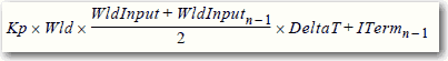
Due to the use of the single-precision floating point values, it is possible. This possibility is dependant on on the values of WLD and KP, for the ITerm value to be small enough, less than 0.0000001, to be lost when adding to the ITermn-1.
For more information regarding the PI instruction, see the Logix5000™ Controllers Process Control and Drives Instructions User Manual, publication 1756-RM006.
Alarm Systems Timeout Changes Require New Download (00069461)
Known Anomaly First Identified as of:
- Firmware Revision 16.024, 1768-L43, 1768-L45
- Firmware Revision 18.011, 1768-L43S, 1768-L45S
- Firmware Revision 18.011, 1769-L23-QBFC1B, 1769-L23E-QB1B, 1769-L23E-QBFC1B
- Firmware Revision 16.022, 1769-L31, 1769-L32C, 1769-L32E, 1769-L35CR, 1769-L35E
Changes made to the Buffer Timeout value for FactoryTalk® Alarm subscribers do not take effect until the existing buffer has been deleted.
The FactoryTalk alarm buffer (stored in Logix controller memory) is designed to persist through power cycles. If you change the Buffer Timeout value (via the Communication Setup dialog in FactoryTalk View SE), the controller does not use the new timeout value until the existing buffer is deleted and then recreated. To force recreation of this buffer, you can either:
- Redownload the project to the controller
- Disconnect the FactoryTalk Alarm subscriber and leave it disconnected until the existing timeout expires.
Cycle Power to Clear a Major Fault
Known Anomaly First Identified as of:
- Firmware Revision 17.005, 1769-L23E-QB1B, 1769-L23E-QBFC1B, 1769-L23-QBFC1B
- Firmware Revision 16.022, 1769-L31, 1769-L32C, 1769-L32E, 1769-L35CR, 1769-L35E
- Firmware Revision 16.024, 1768-L43, 1768-L45
- Firmware Revision 18.011, 1768-L43S, 1768-L45S
If a 1769 I/O fault occurs, you must cycle power to the CompactLogix™ controller after clearing the major fault. I/O communication is not restored until after the power cycle. Never use the fault handling routine to clear local I/O faults. Clear local I/O faults manually on a per case basis, and then the controller must be power cycled.
MSG Execution in Master Slave Configurations (Lgx00083882, Lgx00082610)
Corrected as of:
- Firmware Revision 20.011, 11769-L23E-QB1B, 1769-L23E-QBFC1B, 1769-L23-QBFC1B
- Firmware Revision 20.011, 1769-L31, 1769-L32E, 1769-L32C, 1769-L35E, 1769-L35CR
- Firmware Revision 20.011, 1768-L43, 1768-L45
- Firmware Revision 20.011, 1768-L43S, 1768-L45S
Known Anomaly
- Firmware Revision 18.011, 1769-L23E-QB1B, 1769-L23E-QBFC1B, 1769-L23-QBFC1B
- Firmware Revision 17.005, 1769-L31, 1769-L32E, 1769-L32C, 1769-L35E, 1769-L35CR
- Firmware Revision 17.004, 1768-L43, 1768-L45
- Firmware Revision 18.011, 1768-L43S, 1768-L45S
Unsuccessful MSG execution results in subsequent unsuccessful messages in master/slave controller configurations.
When a DF1 serial connection is used between a master and slave controller, an MSG instruction is not successfully executed and an in-polling sequence error occurs if the master station address is not listed in the poll node list.
However, with this anomaly, after the in-polling sequence error, subsequent MSG instructions are also unsuccessful.
To work around this anomaly, change the master station address of a controller to another value or re-execute the unsuccessful MSG instruction in Master
Transmit mode and use the Between Station Polls parameter.
Time Synchronization Causes Controller to Become Local Master
Known Anomaly First Identified as of:
- Firmware Revision 18.011, 1769-L23E-QB1B, 1769-L23E-QBFC1B, 1769-L23-QBFC1B
- Firmware Revision 18.011, 1769-L31, 1769-L32C, 1769-L32E,1769-L35CR, 1769-L35E
- Firmware Revision 18.011, 1768-L43, 1768-L43S, 1768-L45, 1768-L45S
Enabling the time synchronization feature of a CompactLogix™ controller results in the controller becoming the local master. It does not result in the controller synchronizing with other wallclock times in the system.
Fault/Program States Not Supported by Using the Module Configuration
Dialog Box
Known Anomaly First Identified as of:
- Firmware Revision 17.005, 1769-L23E-QB1B, 1769-L23E-QBFC1B, 1769-L23-QBFC1B
- Firmware Revision 16.022, 1769-L31, 1769-L32E, 1769-L32C, 1769-L35E, 1769-L35CR
- Firmware Revision 16.024, 1768-L43, 1768-L45
- Firmware Revision 18.011, 1768-L43S, 1768-L45S
This anomaly applies to CompactLogix™ systems as follows:
- 1768 CompactLogix™ and 1769 CompactLogix controllers – Local I/O modules
- 1769 CompactLogix packaged controllers – Embedded I/O modules or local I/O modules, also known as expansion I/O modules in this case
In this description, the term I/O module refers to 1769 Compact output modules or output points on 1769 Compact combination modules.
RSLogix™ 5000 software does not support Fault/Program state action for I/O modules in CompactLogix systems. The controller cannot trigger the configured Fault/Program state action. You can configure the Fault/Program state action in RSLogix 5000 software, but the configuration does not take effect.
If either of the following conditions exists, outputs turn off, regardless of the Fault/Program state action configuration:
- The output loses communication with the controller.
- The controller is placed in Program mode.
Additionally, RSLogix 5000 software generates configuration tags for any I/O modules in the project. Some of the tags define configuration (C) data type members that include attributes for Fault/Program states, also known as alternate output states.
Because CompactLogix systems do not support Fault/Program state action for I/O modules, do not configure the attribute tags listed in the following table.
Attribute Tags to Avoid
|
Digital Output Modules
|
Analog Output Modules
|
|
Where CHx = the channel number
|
Multiple Absolute MAM Instructions with S-curve and Merge Enabled Can Overshoot Target Position (00078822)
Known Anomaly First Identified as of:
- Firmware Revision 17.004, 1768-L43, 1768-L45
- Firmware Revision 18.011, 1768-L43S, 1768-L45S
Overshoot can occur with MAM instruction with Merge Enabled if there is not enough distance until the end of the move for the programmed dynamic jerk parameters, that is decel jerk and axis decel, in the merged move.
Overshoot can be avoided by increasing the decel jerk or not using the merge.
Motion Axis Move Instruction May Overshoot Programmed Position (00078822)
Known Anomaly First Identified as of:
- Firmware Revision 18.011, 1768-L43, 1768-L43S, 1768-L45, 1768-L45S
Under some rare occurrences, if a Motion Axis Move (MAM) instruction with Merge Enabled is activated during the deceleration segment of an active MAM instruction then the new MAM instruction can overshoot its programmed endpoint. The occurrence of the overshoot depends on the following factors:
- The original MAM instruction’s remaining travel distance at the time of the merge and the new MAM instruction’s remaining travel distance.
- The relationship of the decel jerk of the new MAM instruction to the decel jerk of the original MAM instruction.
- If the original MAM instruction is decelerating
Typically, the overshoot does not occur. If either of the following conditions exist, you avoid the overshoot.
- The new MAM instruction is programmed with Merge Disabled. If there is no other motion active at the time of the merge, then the Merge Disable results in the same operation as the Merge Enable.
- The new MAM instruction has a slightly higher jerk (in Units/sec3) than the original MAM instruction. Lower value of jerk in % of time results in higher value of jerk (in Units/sec3).
Motion Group Shutdown Reset Instruction Execution Results in Shutdown State Error (00095484)
Known Anomaly First Identified as of:
- Firmware Revision 18.011, 1768-L43, 1768-L43S, 1768-L45, 1768-L45S
If a Motion Group Shutdown Reset (MGSR) instruction is executed while a Motion Group Shutdown (MGSD) is still executing, motion error #7, that is, Shutdown State Error, results.
The purpose of an MGSR instruction is to bring an axis group out of the shutdown state. However, when the scenario that is described in the previous paragraph exists, the MGSR instruction is not executed because the shutdown procedure, which is initiated by the MGSD instruction, has precedence. Thus, the MGSR instruction generates motion error #7 because the shutdown procedure has not completed. The shutdown procedure must complete before any attempt to reset the shutdown.
Corrected as of:
- Firmware Revision 20.011, 1768-L43, 1768-L43S, 1768-L45, 1768-L45S
Known Anomaly First Identified as of:
- Firmware Revision 18.011, 1768-L43, 1768-L43S, 1768-L45, 1768-L45S
In a program that uses a Motion Group Stop (MGS) instruction that is configured with Stop Mode = Fast Disable, the axes in the group must be false, that is, disabled, when the instruction transitions to the PC state. That is, the axis status bit DriveEnableStatus must transition to false.
Due to this anomaly, the axes remain enabled for one Coarse Update after the instruction transitions to the PC state. Once the next Coarse Update is complete, the axes are disabled.
You must delay initiation of other motion instructions until the enable status is cleared.
VelocityFeedback Attribute May Contain Incorrect Value (00107793)
Known Anomaly First Identified as of:
- Firmware Revision 18.011, 1768-L43, 1768-L43S, 1768-L45, 1768-L45S
IMPORTANT: This anomaly only occurs in SERCOS applications that use Kinetix® SERCOS drives and linear motors.w
Under certain conditions, it is possible that the Real-Time Axis attribute VelocityFeedback contains an incorrect value. The inaccuracy is the result of incorrect scaling of that attribute.
Your program has an incorrect value for the VelocityFeedback attribute if you follow these steps.
- While offline, you write your RSLogix™ 5000 program and, as part of that program, the VelocityFeedback attribute is selected.
- You save the program and download it to the controller.
- You go online.
The VelocityFeedback attribute value is incorrect because that attribute was enabled before the program was saved, downloaded, and put online.
Workaround - To avoid this anomaly, do not enable the VelocityFeedback attribute until the RSLogix 5000 program is online.
Corrected as of:
- Firmware Revision 20.011, 1768-L43, 1768-L43S, 1768-L45, 1768-L45S
Known Anomaly First Identified as of:
- Firmware Revision 18.011, 1768-L43, 1768-L43S, 1768-L45, 1768-L45S
When using the 1769 generic profile, if the input and output assembly instances are set to 248 bytes (communications format Data Int) and the module is in slot 1, the connection to the module errors with 203 connection time-out.
Corrected as of:
- Firmware Revision 20.011, 1768-L43, 1768-L43S, 1768-L45, 1768-L45S
Known Anomaly First Identified as of:
Firmware Revision 18.011, 1768-L43, 1768-L43S, 1768-L45, 1768-L45S
The .ACCEL and .DECEL Motion status bits operate differently than in RSLogix™ 5000 programming software, version 17.x, because the axis status bits of the consumed axis are recalculated instead of reusing the axis status bits of the producer axis.
Functional Changes
This release has the following functional changes from the previous release.
V19 Additional Memory Requirements for 1768 CompactLogix Controllers
Functional Change First Identified as of:
- Firmware Revision 19.011, 1768-L43, 1768-L43S, 1768-L45, 1768-L45S
Firmware revision 19.000 or later can require more memory than previous revisions, for example, revision 10.xxx or 11.xxx). To estimate the additional memory that your project can require, use this table.
| If you
upgrade
from
revision
(add all
that
apply)
|
Then add the following memory requirements to your
project
|
Which comes
from this type
of memory
| ||
|
|
Component
|
Increase/Decrease
Per
Instance |
I/O
|
Data
and
Logic
|
|
18.x to
19.x
|
|
<no change>
|
|
|
|
17.x to
18.x
|
Program
|
+ 8 bytes
|
|
ü
|
|
|
Equipment phase
|
+ 20 bytes
|
|
ü
|
|
|
Add-On Instruction
|
+ 12 bytes
|
|
ü
|
|
|
Each tag
In addition, if you use a tag of the types that are listed, increase the memory as indicated for each instance: |
+ 4 bytes
|
|
ü
|
|
|
Produced tag
|
+ 36 bytes + (24
bytes x number of
consumers)
|
ü
|
|
|
|
Consumed tag
|
+ 24 bytes
|
ü
|
|
|
|
Data access control
|
+ 4 bytes per symbol
|
|
ü
|
|
|
Tag that uses ALARM_ANALOG
data type
|
- 20 bytes
|
|
ü
|
|
|
Tag that uses ALARM_DIGITAL
data type
|
+ 28 bytes
|
|
ü
|
|
|
Tag that uses MOTION_GROUP
data type
|
+ 76 bytes
|
|
ü
|
|
|
Tag that uses
AXIS_SERVO_DRIVE or
AXIS_GENERIC_DRIVE data type
|
+ 786 bytes
|
|
ü
|
|
|
Tag that uses AXIS data type other
than AXIS_SERVO_DRIVE or
AXIS_GENERIC_DRIVE |
+ 818 bytes
|
|
ü
|
|
|
Tag that uses
COORDINATE_SYSTEM data type
with no transform dimensions
|
+ 40 bytes
|
|
ü
|
|
|
Tag that uses
COORDINATE_SYSTEM data type
with transform dimensions
|
+ 100 bytes
|
|
ü
|
|
|
Module input connection
|
+ 20 bytes
|
|
ü
|
|
|
Module output connection
|
+ 24 bytes
|
|
ü
|
|
|
Safety controller
|
- 8 bytes
|
|
ü
|
|
|
Safety partner
|
- 8 bytes
|
|
ü
|
|
|
For each controller (> 1K bytes
change):
|
|
|
|
|
|
1756-L6x, 1756-L6xS, 1756-L63XT
|
+ 16728 bytes
|
|
ü
|
|
|
1768-L4x, 1768-L4xS
|
+ 14448 bytes
|
|
ü
|
|
|
1769-L2x
|
+ 35084 bytes
|
ü
|
|
|
|
1769-L31
|
+ 14740 bytes
|
ü
|
|
|
|
1769-L32C, 1769-L35CR
|
+ 35400 bytes
|
ü
|
|
|
|
1769-L32E, 1769-L35E
|
+ 35036 bytes
|
ü
|
|
|
|
1789-L10, 1789-L30, 1789-L60
|
+ 4992 bytes
|
ü
|
|
|
|
PowerFlex® 700S 2
|
+ 55340
|
ü
|
|
|
16.x to
17.x
|
Task
|
+ 4 bytes
|
|
ü
|
|
|
Program
|
+ 4 bytes
|
|
ü
|
|
|
Equipment phase
|
+ 8 bytes
|
|
ü
|
|
|
LD routine
|
+ 12 bytes
|
|
ü
|
|
|
FBD routine
|
- 8 bytes
|
|
ü
|
|
|
SFC routine
|
+ 28 bytes
|
|
ü
|
|
|
ST routine
|
+ 4 bytes
|
|
ü
|
|
|
Add-On Instruction
|
- 12 bytes
|
|
ü
|
|
|
If you use a tag of the types that are
listed, increase the memory as
indicated for each instance:
|
|
|
|
|
|
Produced tag
|
+ [4 bytes + (4 bytes
x number of
consumers)
|
ü
|
|
|
|
Consumed tag
|
+ 8 bytes
|
ü
|
|
|
|
Tag that uses MESSAGE data type
|
+ 4 bytes
|
|
ü
|
|
|
Tag that uses ALARM_ANALOG
data type
|
- 64 bytes
|
|
ü
|
|
|
Tag that uses ALARM_DIGITAL
data type
|
- 28 bytes
|
|
ü
|
|
|
Tag that uses
AXIS_SERVO_DRIVE or
AXIS_GENERIC_DRIVE data type
|
- 34 bytes
(2 bytes x number of output cam execution targets) |
|
ü
|
|
|
Tag that uses AXIS data type other
than AXIS_SERVO_DRIVE or
AXIS_GENERIC_DRIVE |
- 52 bytes
(2 bytes x number of output cam execution targets) |
|
ü
|
|
|
Tag that uses
COORDINATE_SYSTEM data type
of 2 dimensions with 2 transform
dimensions
|
+ 20 bytes
|
|
ü
|
|
|
Tag that uses
COORDINATE_SYSTEM data type
of 3 dimensions with 3 transform
dimensions
|
+ 108 bytes
|
|
ü
|
|
15.x to
16.x
|
If you use a tag of the types that are
listed, increase the memory as
indicated for each instance:
|
|
|
|
|
|
Tag that uses ALARM_ANALOG
data type (with no associated tag
references)
|
+ 16 bytes
|
|
ü
|
|
|
Tag that uses ALARM_DIGITAL
data type (with no associated tag
references)
|
+ 4 bytes
|
|
ü
|
|
|
Tag that uses ALARM_ANALOG
data type (if associated tags are
configured for the
ALARM_ANALOG tag)
|
+ 22 bytes
+ (9 x the number of configured, associated tags) + (3 x the sum of the bytes used by the data type of each of the configured associated tags) For example, an analog alarm moved to V16.03 with two Associated Tags – one DINT (4 bytes) and one STRING (88 bytes) would need to add: 22 + 9(2) + 3(92) = 316 bytes |
|
ü
|
|
|
Tag that uses the
COORDINATE_SYSTEM data type
|
+ 132 bytes
|
|
ü
|
Copyright © 2026 Rockwell Automation, Inc. All rights reserved.
Rockwell Automation, Allen-Bradley, and FactoryTalk are trademarks of Rockwell Automation, Inc.
To view a complete list of Rockwell Automation trademarks please click here.
Trademarks not belonging to Rockwell Automation are property of their respective companies.