Release Notes
Dynamix 1444 Series system for machinery protection or condition monitoring over an Ethernet network
Version 3.002 (released 6/2016)
Catalog Number 1444-DYN04-01RA
Features
This release includes the following system features.
Multiplexing
System feature First Identified as of Firmware Revision 2.002
Catalog Number 1444-DYN04-01RA
Added support for channel multiplexing to allow use of all four input channels even in high bandwidth applications, where only one or two channels can be enabled at any one time.
Redundant Tacho Mode
System feature First Identified as of Firmware Revision 2.002
Catalog Number 1444-DYN04-01RA
The ability to have the DSP switch tacho sources (between T0 and T1 configured sources) if a tacho returns a Not OK.
Module Security
System feature First Identified as of Firmware Revision 2.002
Catalog Number 1444-DYN04-01RA
Changes have been made to module security:
- Module owner credentials (vendor ID and SN) are no longer stored to NV memory such to allow a module power cycle to unlock a module (not normally terminated class 1 I/O connection)
- Compliance mode is no longer used as criteria for allowing a module reset. This feature makesit easier to use software reset to bring module in required out-of-box state for firmware update (API and SIL modes).
- Fixed anomaly to make sure that no reset is allowed when an I/O connection is active or when module is owned.
Wire-Off
System feature First Identified as of Firmware Revision 2.002
Catalog Number 1444-DYN04-01RA
Added support of fixed 30 second hold time.
Ethernet Link
System feature First Identified as of Firmware Revision 2.002
Catalog Number 1444-DYN04-01RA
You can now disable non-used Ethernet ports.
IP Addressing
System feature First Identified as of Firmware Revision 2.002
Catalog Number 1444-DYN04-01RA
Module will now allow direct BOOTP/DHCP mode when address switches are set to any non-fixed IP address (‘000’). Previously a software Type 1 reset or hardware out-of-box (‘888’) reset was required.
X/Y + HPF Application Type
System feature First Identified as of Firmware Revision 2.002
Catalog Number 1444-DYN04-01RA
Added support for X/Y-based Eddy Current Probe measurement with the use of HP filter for overall measurement assessment.
Dynamic Pressure + Filter/Overall Application Type
System feature First Identified as of Firmware Revision 2.002
Catalog Number 1444-DYN04-01RA
Added support for additional dynamic pressure type, which provides single overall output with filter configuration, opposed to special configuration where processing is optimized for fast FFT band updates.
Time Waveform (TWF) Alignment
System feature First Identified as of Firmware Revision 2.002
Catalog Number 1444-DYN04-01RA
When a tacho signal is present, stored and requested TWF data is aligned with the tacho signal, such to ease the phase assessment of time waveform.
Known Anomalies in This Release
This release has the following known anomalies.
Transient Buffer Status Information Display
Corrected Anomaly with Firmware Revision 4.006
Known Anomaly First Identified as of Firmware Revision 3.002
Catalog Number 1444-DYN04-01RA
Buffer status was incorrect. We updated the AOP from version 1.02.05 to version 2.01.41. Update will provide the following buffer status information.
|
Display Status
|
Meaning
|
|
Free
|
Buffer Free (available, ready for a transient event)
|
|
Transient Complete, Data Available
|
Data Ready Normal (transient completed normally, but could be
overwritten by a new event)
|
|
Transient Complete, Data Available, Latched
|
Data Latched Normal (transient completed normally, buffer latched)
|
|
Transient in Progress, delta RPM
|
Transient in progress RPM (delta RPM acquisition in progress)
|
|
Transient in Progress, delta Time
|
Transient in progress Time (delta time acquisition in progress)
|
|
Transient Aborted, Data Available
|
Data Ready Aborted (speed crossed back over the same threshold,
but could be overwritten by a new event)
|
|
Transient Aborted, Data Available, Latched
|
Data Latched Aborted (speed crossed back over the same threshold,
buffer latched)
|
|
Transient Complete, Full, Data Available
|
Data Ready Full (completely filled transient buffer)
|
|
Transient Complete, Full, Data Available, Latched
|
Data Latched Full (completely filled and latched transient buffer)
|
|
Disabled
|
Buffer not allocated/enabled
|
Bulletin 1444 Relay
Corrected Anomaly with Firmware Revision 4.006
Known Anomaly First Identified as of Firmware Revision 3.002
Catalog Number 1444-DYN04-01RA
We updated the AOP from version 1.02.05 to version 2.01.41.
We corrected an issue with the voted alarm pull-down menu. The voted alarm pull-down menu did not update correctly when alarms were activated / deactivated.
Bulletin 1444 Filters, FFT, Bands, Demand
Corrected Anomaly with Firmware Revision 4.006
Known Anomaly First Identified as of Firmware Revision 3.002
Catalog Number 1444-DYN04-01RA
We updated the AOP from version 1.02.05 to version 2.01.41.
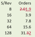
Corrected the displayed number of orders for synchronous FMAX for 8 samples/rev and 128 samples/rev selections. Round-off error caused confusion, particularly with 8 s/rev where users expected 2x to be included.
Bulletin 1444 Sense Control for Complementary Differential Expansion
Corrected Anomaly as of Firmware Revision 4.006
Known Anomaly First Identified as of Firmware Revision 3.002
Catalog Number 1444-DYN04-01RA
AOP version 1.02.05 updated to AOP version 2.01.41
Sense control is enabled for Complementary Differential Expansion measurements.
Bulletin 1444 Buffered Outputs
Corrected Anomaly with Firmware Revision 4.006
Known Anomaly First Identified as of Firmware Revision 3.002
This is a hardware change. The change is effective beginning with modules manufactured after 13 July 2017.
Catalog Number 1444-DYN04-01RA
• Buffered outputs susceptible for injected common-mode noise
• BNC output operational limitations
Buffered output circuit are modified to eliminate injected common-mode noise, and to make the BNC and terminal pin outputs equivalent with respect to performance.
Revised Buffered Output Specifications
|
Buffered Outputs (4)
| |||
|
Buffered
Output
|
Resistance
(Ω)
|
Protection
| |
|
ESD/EFT
|
Surge
| ||
|
BNC
|
100
|
Yes
|
No
|
|
For temporary connection to instruments such as portable data collectors or analysis systems over short distances (32 ft / 10 m).
| |||
|
Terminal
Pins
|
100
|
Yes
|
Yes
|
|
For permanent connections to instruments or when long cable runs (328 ft / 100 m) are required.
| |||
|
Power
|
Buffered outputs operating power: approximately 0.8 W
| ||
|
May be enabled/disabled with a local switch to reduce power requirement and heat load when not required.
| |||
|
Notes
|
All outputs are single ended and have no isolation.
| ||
|
Buffered output is not representative of input when no load (sensor) is connected to the associated measurement channel.
| |||
|
Confirm that the connected instrumentation does not provide power, such as if to power an accelerometer, to the buffer output.
| |||
1444 Reset Behavior Changes
Corrected Anomaly as of Firmware Revision 4.006
Known Anomaly First Identified as of Firmware Revision 3.002
Catalog Number 1444-DYN04-01RA
Type 0 Reset
Previous behavior would only reset the Auxiliary processor and therefore did not mimic the power startup behavior.
New behavior is that both the Aux Processor and the DSP are restarted.
Type 1, 2 Out of Box Reset
Main functionality is to return the module to Out‐of‐Box defaults.
Previous behavior would reset Auxiliary processor and DSP and upon boot load default configuration to DSP.
New behavior will not reset DSP, but will activate default configuration, reset Auxiliary processor that will then reconfigure DSP with default configuration and restart data acquisition.
4-20 mA Output in Transducer Fault Condition
Corrected Anomaly as of Firmware Revision 4.006
Known Anomaly First Identified as of Firmware Revision 3.002
Catalog Numbers: 1444-DYN04-01RA
When you are using the Analog Output Module…
Corrected error where 4‐20 mA output channels 1, 2, and 3 (channel 0 OK) would not output defined high or low (typically low) current output to indicate Transducer Fail condition.
Aux Bus Communications when configured for 20 kHz measurements
Corrected Anomaly as of Firmware Revision 4.006
Known Anomaly First Identified as of Firmware Revision 3.002
Catalog Number 1444-DYN04-01RA
An anomaly has been corrected where a module configured for ≥20 kHz could force an ExpBusOrExpModuleFault indication.
For heavily loaded configurations (for example, 20 kHz), the allotted loop processing time may be too short to process all tasks. For these conditions, the typical loop time of 47 ms can be extended to ensure all tasks will be completed.
A problem has been detected in how this algorithm was applied to 20/40 kHz applications and additional algorithm optimization has been applied to keep heavy loaded 20 kHz configurations within 100 ms process time.
Note that the ModuleLoadWarning and ProtectionPerformanceWarning status tags will be set as appropriate when the loop time exceeds 47 or 100 milliseconds, respectively.
Synchronous Sampling-based Transient
Corrected Anomaly as of Firmware Revision 4.006
Known Anomaly First Identified as of Firmware Revision 3.002
Catalog Number 1444-DYN04-01RA
Corrected behavior where transient trigger would occur in sample buffer data time
period, which can be long based upon synchronous sampling at low startup speed, such
that pre‐trigger data would be included in transient data. Occasionally this effect could
also capture data exceeding the high level RPM threshold.
Sample data block processing has now been replaced with RPM trigger and sample time trigger filter to prevent data storage outside low and high threshold levels.
Run‐up Transient at Module Startup
Corrected Anomaly as of Firmware Revision 4.006
Known Anomaly First Identified as of Firmware Revision 3.002
Catalog Number 1444-DYN04-01RA
Corrected issue where a run up transient would be logged (incomplete, single
measurement value) in case module would startup with an active speed signal higher
than run‐up low RPM threshold.
DSP Reconfiguration – Trip Inhibit Extension
Corrected Anomaly with Firmware Revision 4.006
Known Anomaly First Identified as of Firmware Revision 3.002
Catalog Numbers: 1444-DYN04-01RA
During process that Aux Processor sends configuration to DSP, the Aux Processor will issue a trip Inhibit during reconfiguration and also speeds up the DSP to optimize reconfiguration time. When DSP report first ready state, used to disable DSP speed-up process, the trip inhibit was also disabled, but as further settling may be required as result of enabling normal configuration, the next DSP ready state is now used to disable the Trip Inhibit and as such eliminates potential alarming as result of final settling.
Disabled Measurement Alarm no longer allowed in Voted Alarm Logic
Corrected Anomaly with Firmware Revision 4.006
Known Anomaly First Identified as of Firmware Revision 3.002
Catalog Numbers: 1444-DYN04-01RA
The AOP will no longer allow a configuration that includes voted alarms that reference disabled measurement alarms. However, in addition, the Aux Processor firmware has implemented a second level configuration validation scheme where for each voted alarm the used measurement alarm input is validated to be enabled. In case of detected issues, the configuration will be rejected as FW cannot force enable of alarms nor disable of active voted alarms or ignore disabled measurement alarm inputs. It is simply handled as a bad configuration.
Expansion Module Hot Swap
Corrected Anomaly with Firmware Revision 4.006
Known Anomaly First Identified as of Firmware Revision 3.002
Catalog Numbers: 1444-DYN04-01RA
Note that with the ExpansionModuleSummary status set, a configuration write will be forced even if the ‘existing’ configuration is just being refreshed (no difference is required).
Bulletin 1444 Electronic Keying
Corrected Anomaly with Firmware Revision 4.006
Known Anomaly First Identified as of Firmware Revision 3.002
Catalog Numbers: 1444-DYN04-01RA
We also resolved an issue that prevented changing the Keying selection while online.
Known Anomalies from Previous Releases
These anomalies are from previous releases but are still known in this release.
Pre-Filter Source Selection
Known Anomaly First Identified as of Firmware Revision 2.002
Catalog Number 1444-DYN04-01RA
For Add-on Profile Version 79, the Pre-Filter signal source selection is no longer supported but remains a selection on some menus. Pre-Filter is now the same as ADC-Out.
Alternate Path Source Selection
Known Anomaly First Identified as of Revision 2.002
Catalog Number 1444-DYN04-01RA
For the Add On Profile Version 79, the Alternate Path signal source selection is selectable even when Alternate Path signal processing is OFF.
ADC-out Source Selection
Known Anomaly First Identified as of Revision 2.002
Catalog Number 1444-DYN04-01RA
For the Add On Profile Version 79, the ADC-out signal source selection should not be selectable when using a 40 kHz Module Personality.
Module Definition Default Unicast Setting
Known Anomaly First Identified as of Revision 2.002
Catalog Number 1444-DYN04-01RA
When Module Definition changes are made the AOP will reset the Unicast selection to default.
Time Sync
Known Anomaly First Identified as of Firmware Revision 2.002
Catalog Number 1444-DYN04-01RA
In some cases, the module can report that it is synced when it has large discrepancies in System Time.
Redundant Controllers Support
Known Anomaly First Identified as of Firmware Revision 2.002
Catalog Number 1444-DYN04-01RA
Support for redundant controllers is not provided.
gSE FFT Improperly Scaled
Known Anomaly First Identified as of Firmware Revision 2.002
Catalog Number 1444-DYN04-01RA
gSE FFT data, as read by software, is off (high) by a factor of 2.828.
Module Firmware May Default to Recovery Mode
Known Anomaly First Identified as of Firmware Revision 2.002
Catalog Number 1444-DYN04-01RA
During pulsed power cycles, it is possible for the module to fault to Recovery mode, which requires you to update the firmware. This can occur if power is lost while the firmware is updating nonvolatile memory.
4…20 mA Output Measurement Wrapping
Known Anomaly First Identified as of Revision 2.002
Catalog Number 1444-DYN04-01RA
If the measurement value is much larger than the configured scale, the 4…20 mA value may wrap around as normal measurement result.
Application Notes
This release has the following application notes.
Use Local Bus Extension Cables
Application Notes
Catalog Number 1444-DYN04-01RA
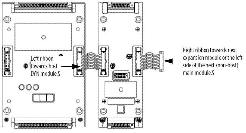
The system is designed to be installed in a specific manner. Expansion modules fit to the right-hand side. The base-mounted headers are latched and, for additional security, cannot be removed (or inserted) while there is a module in place on that base.
For more information, see Dynamix 1444 Monitoring System User Manual, publication 1444-UM001 .
Voted Alarm Status Values
Application Notes
Catalog Number 1444-DYN04-01RA
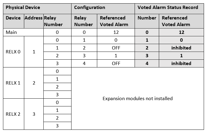
IMPORTANT: Voted Alarm Status records do not associate 1:1 to the 13 Voted Alarm definitions. Reference the Alarm Number attribute (bits 10-13) of each Voted Alarm Status record to identify the Voted Alarm that the entry applies to.
Voted Alarm Status Record Assignment
Voted Alarm Status records are applied first to physical relay. This assures that every physical relay has an associated Voted Alarm Status record even if the relay is not used. For example, if an application includes one 1444-REX00-04RB Expansion Relay module (address 1) and the configuration enabled relays 0 and 2 from the expansion module referencing them to Voted Alarms 0 and 1, plus enabled the main module’ s onboard relay with it referencing Voted Alarm 12, then the Voted Alarm Status records would be allocated as shown here:
Once Voted Alarm Status records are allocated to any physical relays, any remaining Voted Alarm Status records will be assigned to any Voted Alarms that were not already assigned, having been associated with a physical relay. This allocation is done simply by assigning unreferenced enabled Voted Alarms, in order, to the next available Voted Alarm Status record. For example, if the above configuration also enabled voted alarms 7-11 to use as ‘ virtual’ alarms, then the Voted Alarm Status record allocation would be:
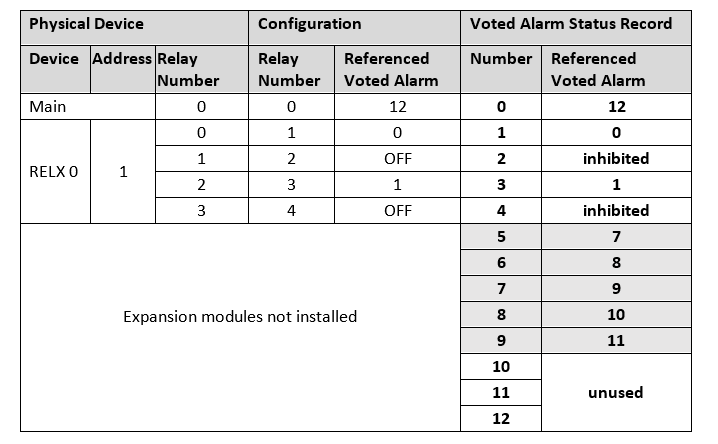
Note that it is possible for an enabled Voted Alarm that is not referenced by a physical relay to not be referenced by a Voted Alarm Status record.
For more information, see Dynamix 1444 Monitoring System User Manual, publication 1444-UM001 .
Bulletin 1444 ODVA Compliance
Application Notes First Identified as of Firmware Revisions 3.002 and 4.006
Catalog Number 1444-DYN04-01RA
Compliant to ODVA Test Reference CT14
Firmware revision 3.002 was compliant to ODVA test reference CT11 (CIP Protocol Rev 3.14 and EIP adaption Rev 1.15).
Firmware revision 4.006 is compliant to ODVA test reference CT14 (CIP Protocol Rev 3.21 and EIP adaption Rev 1.22) and self-test CT15.
Copyright © 2024 Rockwell Automation, Inc. All rights reserved.
Rockwell Automation, Allen-Bradley, and FactoryTalk are trademarks of Rockwell Automation, Inc.
To view a complete list of Rockwell Automation trademarks please click here.
Trademarks not belonging to Rockwell Automation are property of their respective companies.