Release Notes
20G - Firmware versions and revisions can be found in the Versions tab above
Version 9.001 Unsigned (released 8/2013)
Catalog Number PowerFlex 755 (series A)
Requirements
This release has the following requirements.
System Requirements Identified as of PowerFlex 755 Drive Firmware Revision 3.004
The new Auto/Manual HIM Preload feature requires firmware in the HIM that is newer than 1.007.
System Requirements Identified as of PowerFlex 755 Drive Firmware Revision 3.004
System Requirements Identified as of PowerFlex 753 Drive Firmware Revision 5.001
The Customer Configurable Response to HIM Communications Loss feature requires a new enhanced style HIM (20-HIM-A6, 20-HIM-C6S). This feature will not work with older contemporary 7-Class HIM’ s (20-HIM-A3, 20-HIM-A5, 20-HIM-C3S, 20-HIM-C5S).
EtherNet/IP Port and 20-750-ENETR Require Quality of Service (QoS)
System Requirements Identified as of PowerFlex 755 Drive Firmware Revision 9.001
System Requirements Identified as of PowerFlex 753 Drive Firmware Revision 9.001
With this firmware revision, the EtherNet/IP port and 20-750-ENETR require the EtherNet/IP scanner to use a compatible method of specifying Quality of Service (QoS). The following table details the compatible products and firmware revisions.
|
Product
|
Compatible Rev. No.
|
|
DriveLogix 5730 Embedded
Ethernet Port
|
Rev. 3.1.4
|
|
CompactLogix (1769-L2x/L3x)
|
Rev. 17.03
|
|
ControlLogix (1756-ENBT)
|
Rev. 4.005
|
|
CompactLogix (1768-ENBT)
|
Rev. 2.001
|
|
FlexLogix (1788-ENBT)
|
Rev. 2.004
|
|
ControlLogix 1756-EN2T (F)(XT)
|
No Update needed
|
|
SoftLogix I/O Messaging
|
No Update needed
|
Drive Firmware, Series, and Frame Size Compatibility Requirements
System Requirement Identified as of PowerFlex 755 Drive Firmware Revision 3.004
The following table identifies firmware revisions and the PowerFlex 755 drive series and frame sizes with which they are compatible:
|
Firmware
Revision
|
Compatible with Drive
Series
|
Compatible with Drive Frame
Size
|
|
2.xxx
|
A
|
2…8
|
|
3.xxx…5.xxx
|
A
|
2…7
|
|
B
|
8 and 9
| |
|
6.xxx…7.xxx
|
A
|
1…7
|
|
B
|
8 and 9
| |
|
8.xxx and
Later
|
A
|
1…7
|
|
B
|
8…10
|
Features
This release includes the following system features.
System Feature Identified as of:
- PowerFlex 755 Drive Firmware Revision 9.001
- PowerFlex 753 Drive Firmware Revision 9.001
This revision of drive firmware adds profiles to support the 11-Series I/O and ATEX option cards listed in the table below. These profiles allow for the configuration through normal drive startup procedures including the HIM assisted startup and drive software tool wizards. Parameter and fault information can be found in the PowerFlex 750-Series AC Drives Programming Manual, publication 750-PM001.
|
Catalog Number
|
Module Description
|
|
20-750-1132C-2R
|
24V DC I/O Option Card with 3Digital Inputs, 2
Relay Outputs, 1 Analog Input, and 1 Analog
Output
|
|
20-750-1133C-1R2T
|
24V DC I/O Option Card with 3 Digital Inputs, 1
Relay Output, 2 Transistor Outputs, 1 Analog
Input, and 1 Analog Output
|
|
20-750-1132D-2R
|
115V AC I/O Option Card with 3 Digital Inputs, 2
Relay Outputs, 1 Analog Input, and 1 Analog
Output
|
|
20-750-ATEX
|
ATEX Option Card with 1 Thermosensor Input
Connection
|
System Feature Identified as of PowerFlex 755 Drive Firmware Revision 9.001
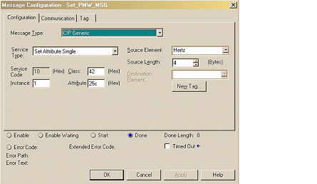
In CIP Motion Mode, customers can now control the PWM carrier frequency by changing Motion Device Axis Object attribute number 604. This can be done in the controller. Below is a sample configuration for a message command that can be applied in CIP Motion Mode. Knowledgebase document 550530 can also be referenced for a sample configuration setup.
System Feature Identified as of PowerFlex 755 Drive Firmware Revision 9.001
This revision of drive firmware allows customer to use the Drive NV functionality, to control Interior Permanent Magnet (IPM) motors in CIP Motion mode. This can be accomplished by commissioning the drive in standalone or IO mode. The next step is to connect the drive to the controller in CIP motion mode. In RSLogix or Studio 5000, the motor selection is set to Drive NV. The Drive NV selection enables the controller to read the motor and tuning settings from the drive for use in CIP Motion.
Corrected Anomalies in This Release
This release corrects the following anomalies.
CORRECTED with PowerFlex 755 Drive Firmware Revision 9.001
CORRECTED with PowerFlex 753 Drive Firmware Revision 9.001
When the drive experiences a 900 level exception, select PowerFlex 750-Series option cards remain in the last known state and may not fault. The last known state of the option card may differ from the default or startup state. This revision of drive firmware will fault the option card when the drive experiences a 900 level exception therefore making the behavior consistent for all drive status conditions previously mentioned.
CORRECTED with PowerFlex 755 Drive Firmware Revision 9.001
This revision of drive firmware changes the behavior of the thermal model, for all high power drives frames 8… 10, in conditions where the main blower is in a slowed or stopped condition. Under this operating condition the thermal trip and fault limits are adjusted to appropriately account for the changes in the blower fan speed.
Known Anomalies from Previous Releases
These anomalies are from previous releases but are still known in this release.
Known Anomaly First Identified as of PowerFlex 755 Drives Firmware Revision 3.004
Known Anomaly First Identified as of PowerFlex 753 Drives Firmware Revision 5.001
The HIM startup on the PowerFlex 755 drive includes a feedback device selection step. Depending on the option modules installed, that step may first ask the user to choose a port, then a parameter. In some situations, the list of ports incorrectly shows multiple copies of 'Port 0 - PowerFlex 755' followed by the feedback port/module.
The incorrect behavior happens only under the following conditions:
- It is the first time that startup feedback selection has been run since flashing the drive.
- The feedback module is a dual encoder or UFB and no other option modules are installed.
- A reset to defaults of the drive NVS parameters has not been performed since the drive was last flashed.
When the incorrect port list appears, it is still possible to successfully select the feedback module port by following one of these methods.
- Scroll past the multiple copies of Port 0 to reach the desired feedback module.
- Press the Esc soft key to back up one screen, then select Feedback and press the Enter soft key to display the port selection screen a second time. This time the correct list will be shown.
Known Anomaly First Identified as of PowerFlex 755 Drives Firmware Revision 8.001
Known Anomaly First Identified as of PowerFlex 753 Drives Firmware Revision 8.001
In an application with the use of a PowerFlex 755 or PowerFlex 753 along with the 20-750-ENETR dual port Ethernet/IP module, a persistent stop command may appear in some cases. The action of disconnecting the Ethernet cable from the 20-750-ENETR module, which will result in the drive stopping, may follow with a nuisance fault action. This fault action previously noted is persistent communication of stop commands.
Known Anomaly First Identified as of PowerFlex 755 Drives Firmware Revision 8.001
Known Anomaly First Identified as of PowerFlex 753 Drives Firmware Revision 8.001
In an application with the use of a PowerFlex 755 or PowerFlex 753 along with the 20-750-ENETR dual port Ethernet/IP module, in which a user attempts to save all parameters using DriveExplorer® in some causes the save execution does not complete. When attempting to execute the save all parameters in DriveExplorer the software tool enters an infinite loop and does not progress through the save in some instances. To exit the loop, press the cancel button and check if the text file has been saved.
Known Anomaly First Identified as of PowerFlex 755 Drive Firmware Revision 2.011
Known Anomaly First Identified as of PowerFlex 753 Drive Firmware Revision 7.001
You cannot change the level of current used during the direction test on a permanent magnet motor while in Integrated Motion on EtherNet/IP (CIP Motion) mode. It is set at 10%. If the system requires more than 10% to turn the motor, it will fail to perform the test.
Known Anomaly First as of PowerFlex 755 Drive Firmware Revision 2.011
The protection algorithms in frame 8 drives create false 168 “PWM Freq Reduced” exception events when running at zero speed. These can occur when the drive is first energizing the motor and establishing motor flux.
Known Anomaly First Identified as of PowerFlex 755 Drive Firmware Revision 3.004
Known Anomaly First Identified as of PowerFlex 753 Drive Firmware Revision 5.001
The following internal diagnostic items may contain incorrect data after upgrading a PowerFlex 755 from revision 1 to revision 6 firmware: 2 [PBLT Pwrup Time], 3 [PBLT GatesOnTime], 4 [PBLT Mtr MW Hrs], 5 [PBLT Rgn MW Hrs] and 67 [PwrBd Pwr Cycles].
The following parameters may contain incorrect data after upgrading a PowerFlex 755 from revision 1 to revision 6 firmware: 13[Elapsed MWH], 14 [Elapsed kWH], 15 [Elapsed Run Time], 16 [Elpsd Mtr MWHrs], 17 [Elpsd Rgn MWHrs], 18 [Elpsd Mtr kWHrs], 19 [Elpsd Rgn kWHrs], 490 [HSFan ElpsdLife], 497 [InFan ElpsdLife], 503 [MtrBrngElpsdLife], 508 [MtrLubeElpsdHrs], 512 [MchBrngElpsdLife] and 517 [MchLubeElpsdHrs].
These values will affect the associated calculated “ remaining life ” parameter values and predictive maintenance events.
Known Anomaly First Identified As of PowerFlex 755 Drive Firmware Revision 3.004
This anomaly affected customers using Integrated Motion on EtherNet/IP (CIP Motion). If you attempted to use Drive NV when configuring the motor on a motion axis with a PowerFlex 755, the drive would not return the appropriate error. This feature is not currently supported in the PowerFlex 755.
Known Anomaly First Identified as of PowerFlex 755 Drive Firmware Revision 8.001
The drive may throw an F927 fault when an axis is inhibited. If this occurs, the drive will shut down allowing the motor to coast. The status LED will blink 27 times, pause, then repeat. If this occurs, cycle power to the drive to clear the fault.
Known Anomaly First Identified as of PowerFlex 755 Drive Firmware Revision 6.004
Known Anomaly First Identified as of PowerFlex 753 Drive Firmware Revision 6.004
When running in Flux Vector open loop mode for induction motor or Interior Permanent Magnet (IPM) motor mode, the drive may experience an F918 exception event when the motor accelerates through a 7 Hz operating frequency due to the simultaneous transition from a 2 to 4 KHz carrier frequency. This exception can be avoided by setting parameter 40 [Mtr Options Cfg] bit 9 – PWM FreqLock], which will keep the carrier frequency at 4 KHz.
Application Notes
This release has the following application notes.
Application Notes
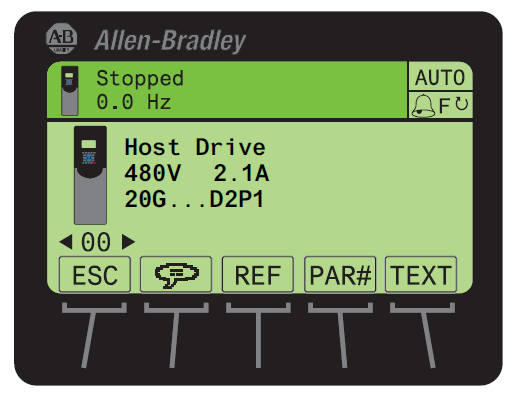
Use the Drive LCD HIM
- Access the Status screen, which is displayed on HIM power up.
- Use the
 or
or  key to scroll to Port 00 for the Host Drive.
 - Press the
 key to display its last-viewed folder.
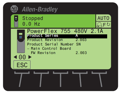
 - Use the
 or
or  key to scroll to the DIAGNOSTIC folder.
 - Use the
 or
or  key to select Device Version.
 - Press the
 (Enter) key to display device version information.
FW Revision is listed under – Main Control Board.
Use DriveExplorer Lite/Full
Important: You need DriveExplorer version 6.01 or later to interface with the PowerFlex 755 drive. To obtain the latest version, visit the Allen-Bradley Web Updates site located at http://www.ab.com/support/abdrives/webupdate
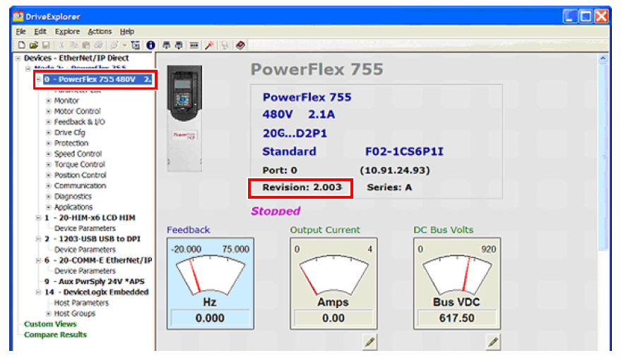
- Launch DriveExplorer and go online with the PowerFlex 755 drive. To connect to the drive, use a 1203-USB converter, a 1203-SSS converter, or an EtherNet/IP network connection.
- In the Devices hardware view, select the PowerFlex 755 drive.
Once selected, information regarding the PowerFlex 755 drive is shown in the right panel including the current firmware revision number.
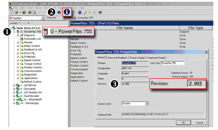
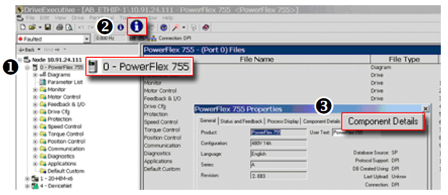
Use DriveExecutive
Important: You need DriveExecutive version 5.01 or later to interface with the PowerFlex 755 drive. To obtain the latest version, visit the Allen- Bradley Web Updates site located at http://www.ab.com/support/abdrives/webupdate
- Launch DriveExecutive and go online with the PowerFlex 755 drive. To connect to the drive, use a 1203-USB converter, a 1203-SSS converter, or an EtherNet/IP network connection.
- In the Drives hardware view, select the PowerFlex 755 drive (
 ).
). - Click the information icon (
 ) to display the drive’
s Properties dialog box.
) to display the drive’
s Properties dialog box.
In the Properties dialog box the “
Revision:”
field (![]() ) will show the drive
’s
current firmware revision number.
) will show the drive
’s
current firmware revision number.
Product Updates and Replacements
Flashing can be performed using a 1203-USB or 1203-SSS converter. For information on connecting either converter to your drive, refer to the 1203-USB USB Converter User Manual, publication DRIVES-UM001, or 1203-SSS Smart Self-powered Serial Converter User Manual, publication 20COMM-UM001.
Note: Images are shown for example only. They are not intended to identify the exact firmware version to which you are updating. Therefore, do not use the data in the images as input or selections for your update.
Frame 8 and Larger Drives
When a Frame 8 or larger drive is flashed with firmware earlier than V4, a F361 “Rerate See Manual” fault will result.
- Confirm the drive's current configuration by viewing Port 10, P21 [Effctv I Rating].
- Save the current parameter settings using the Human Interface Module (HIM), DriveExecutive, or DriveExplorer.
- Perform the flash update.
When concluded, an F361 “Rerate See Manual” fault is indicated.
- Set Port 10, P20 [Recfg Acknowledg ] to 1 “Acknowledge” to accept the reconfiguration.
Important: Drive parameters are set to factory defaults when the reconfiguration is acknowledged. If a condition exists that does not allow the drive parameters to be set to factory defaults, setting P20 to 1 “Acknowledge” will not be accepted. Such conditions include the drive is currently running, DeviceLogix is currently running, or the drive is communicating with a PLC.
- Download the saved drive configuration.
- Confirm the motor and drive ratings before running the drive.
Install the Flash Kit
- Install the flash kit utility for the PowerFlex 755 drive, which includes the latest version of the ControlFLASH utility and deploys firmware files for using HyperTerminal on your computer.
- You are now ready to use DriveExplorer, DriveExecutive, ControlFLASH or HyperTerminal to update the drive.
Use DriveExplorer Lite/Full to Flash Update
- With the Flash Kit installed (see “Install the Flash Kit”), launch DriveExplorer and go online (via a 1203-USB or 1203-SSS converter) with the PowerFlex 755 drive.
- In the Devices hardware view, select the PowerFlex 755 drive (
 ).
). - Click the information icon (
 )to display the drive’s Properties dialog box.
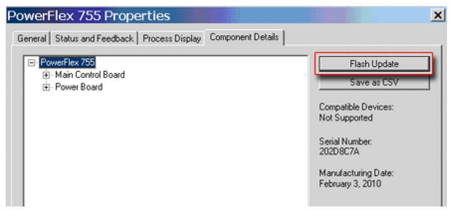
 - In the Properties dialog box, click the Component Details tab (
 ).
).
- With the Main Control Board selected, click Flash Update.
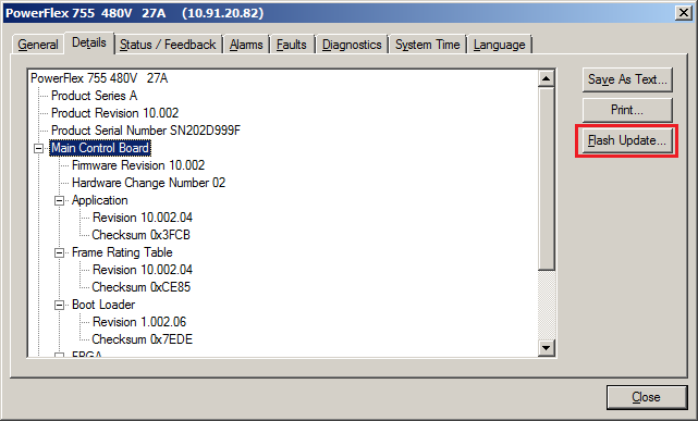
Important: Flash updating the device firmware may cause the device to load defaults. It is recommended that you save the setting to your PC before proceeding.
- From the list of available updates, select the desired firmware revision and click Next >.
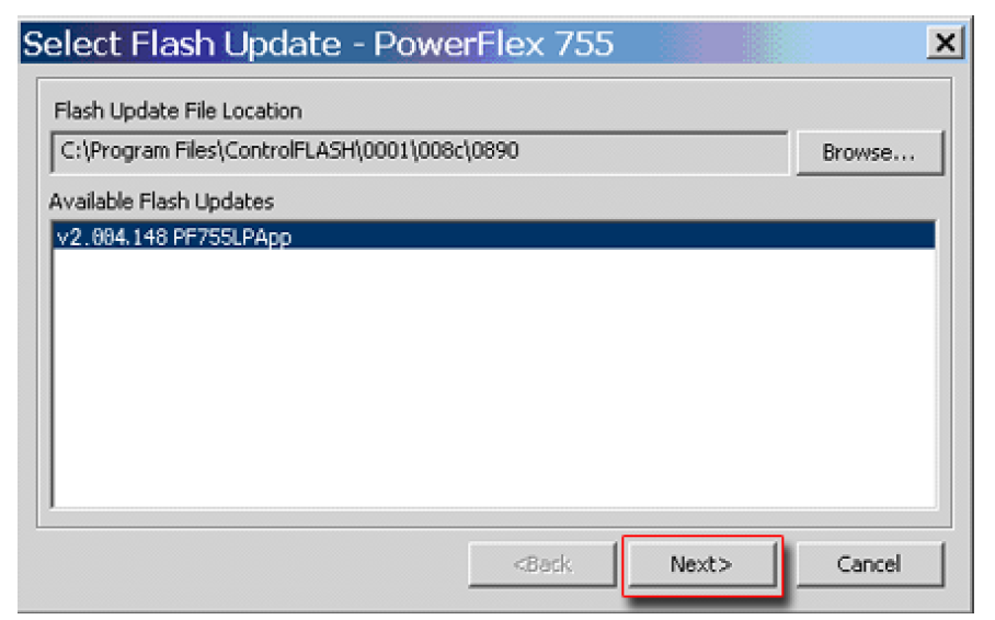
- Follow the remaining prompts until the flash update procedure completes and displays the new firmware revision.
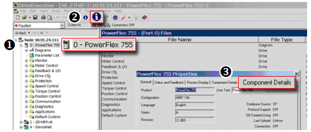
Use DriveExecutive to Flash Update
- With the Flash Kit installed, launch DriveExecutive and go online (via a 1203-USB or 1203-SSS converter) with the PowerFlex 755 drive.
- In the Drives hardware view, select the PowerFlex 755 drive (
 ).
). - Click the information icon (
 )to display the drive’s Properties dialog box.
 - In the Properties dialog box, click the Component Details tab (
 ).
).
- With the PowerFlex 755 drive selected, click Flash Update.
- From the list of available devices, select the PowerFlex 755 drive and click Next >.
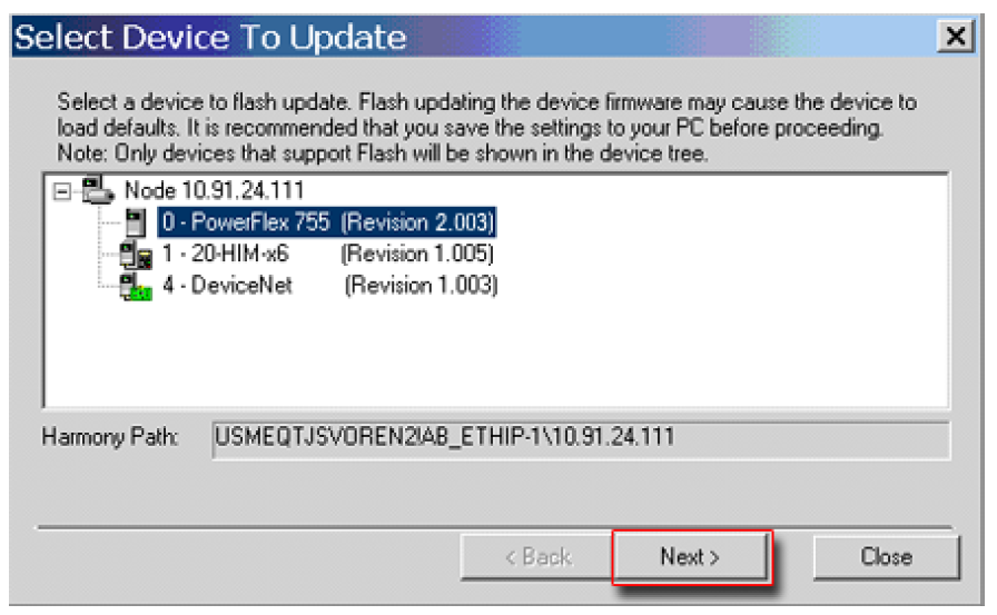
Important: Flash updating the device firmware may cause the device to load defaults. It is recommended that you save the setting to your PC before proceeding.
- From the list of available updates, select the desired firmware revision and click Next >.
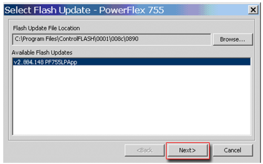
- Follow the remaining screen prompts until the flash update procedure completes and displays the new firmware revision.
Use ControlFLASH to Flash Update
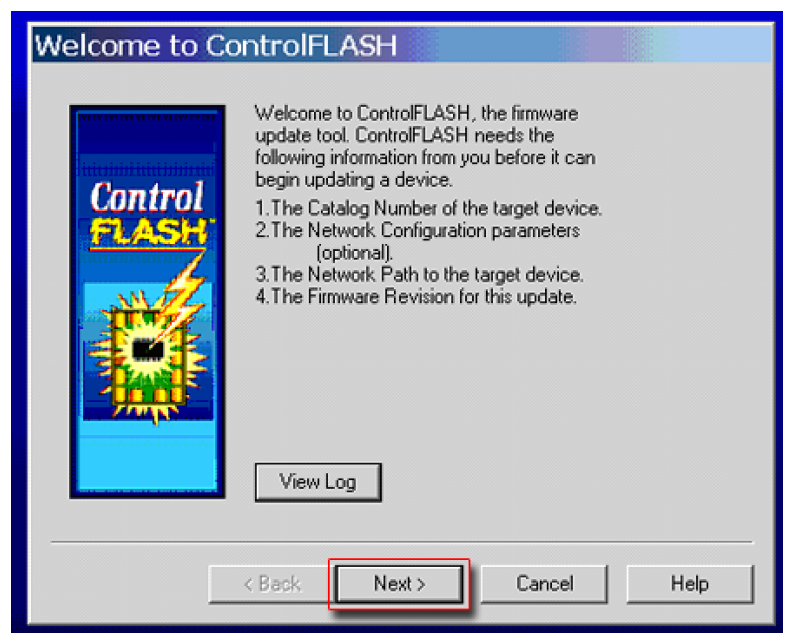
- With the Flash Kit installed, launch ControlFLASH by selecting Start > (All) Programs > Flash Programming Tools > ControlFLASH.
- On the ControlFLASH Welcome screen, click Next >.
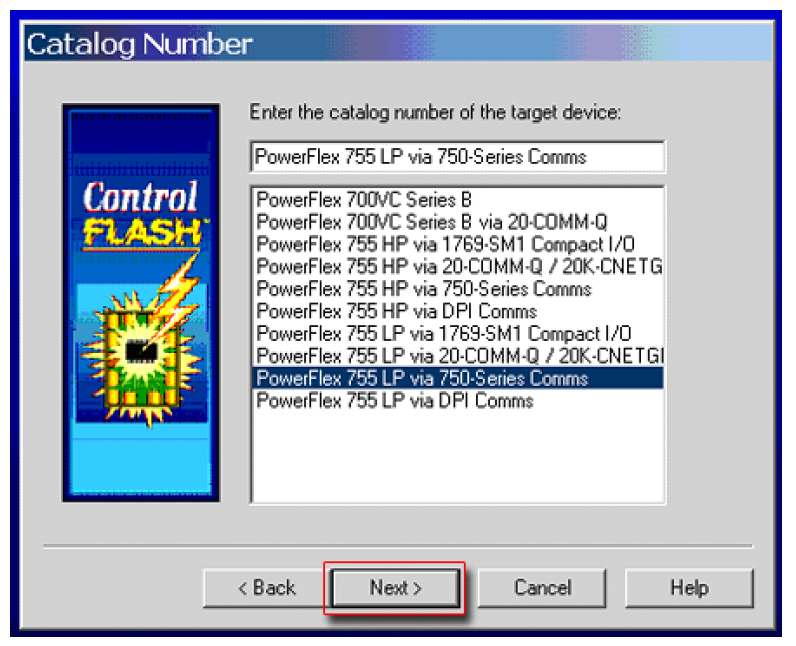
- The Catalog Number dialog box appears. From the list, choose the communication device you will use to update the PowerFlex 755 drive. In the figure below, the embedded EtherNet device is selected.
Once the appropriate communication device is selected, click Next >.
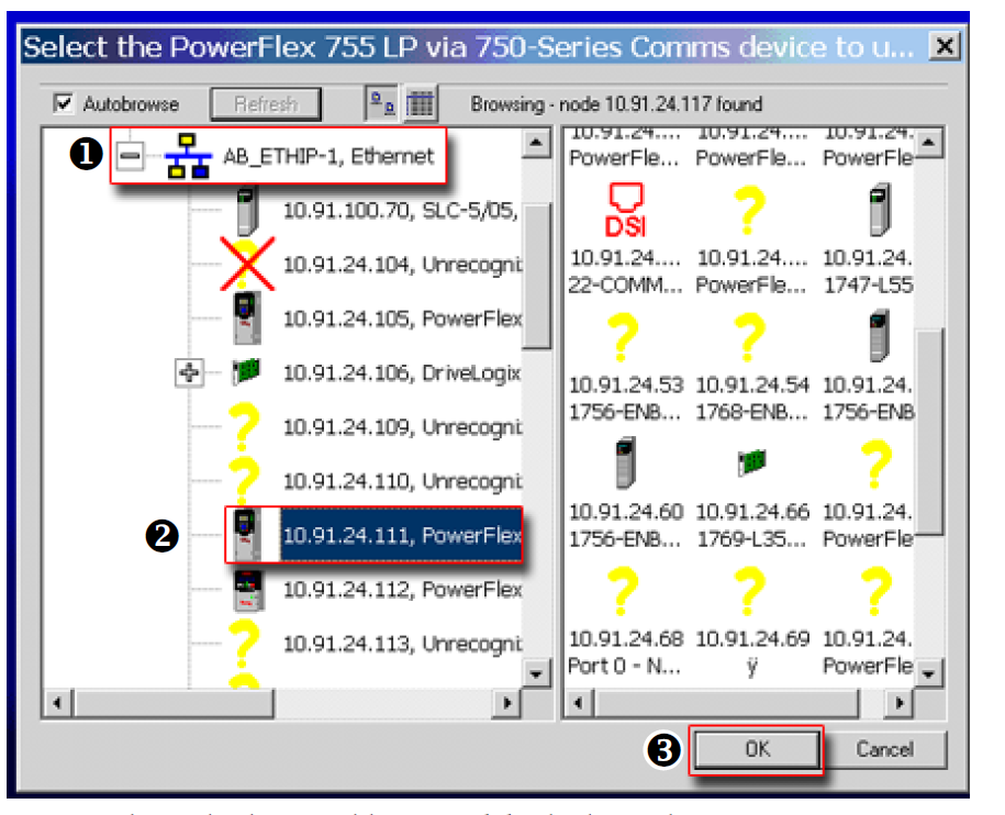
- Now that the correct communication device has been selected, you must select
which device is being updated. With the Select the PowerFlex… dialog box
displayed, follow these steps.
- Expand the hardware view for the communication path you are using (
 ).
). - Select the drive icon that represents the PowerFlex 755 drive you are
updating (
 ).
). - Click OK (
 ).
).
- Expand the hardware view for the communication path you are using (
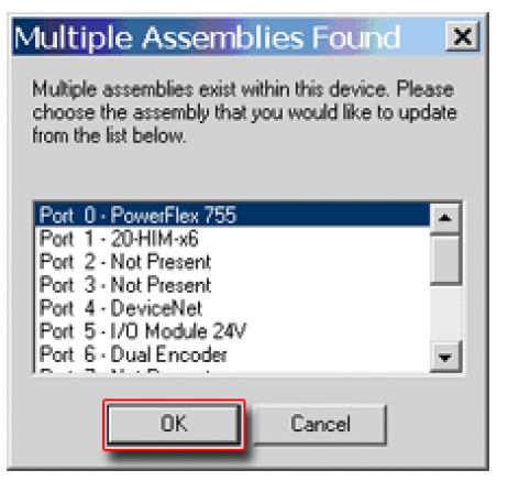
- In the Multiple Assemblies Found display box, select “Port x-PowerFlex 755” from the list and click OK.
- In the Firmware Revision dialog box, select the desired firmware revision from the list of available updates and click Next >.
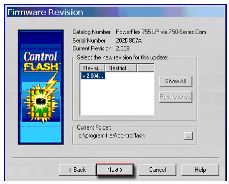
- Follow the remaining prompts until the flash procedure completes and displays the new firmware revision.
Use HyperTerminal to Flash Update
Important: The HyperTerminal process takes at least one hour to complete.
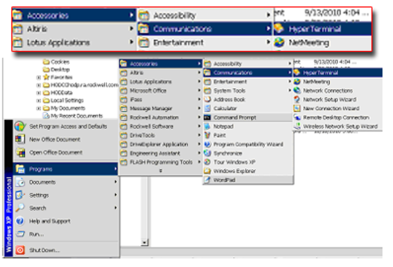
- With the Flash Kit installed, access and launch HyperTerminal as shown below.
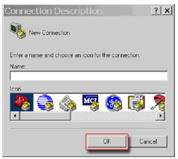
- A New Connection dialog box appears.
- Enter the connection device name in the Name field or select an icon from the library.
- Click OK once you have finished.
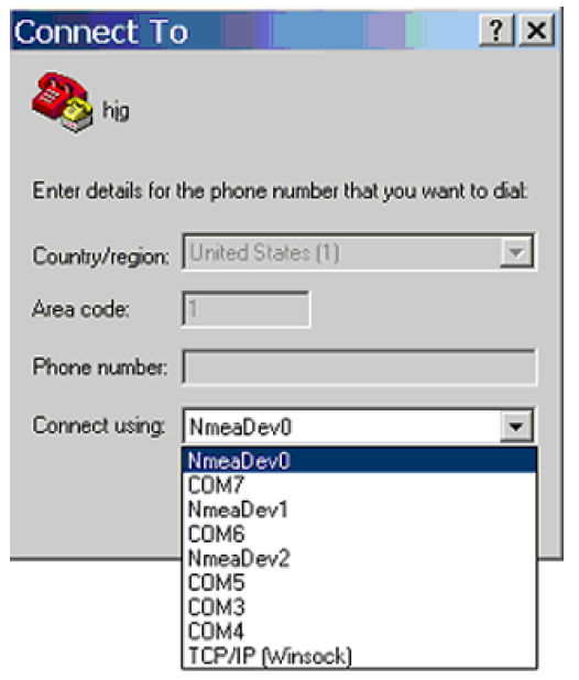
- A Connect To dialog box appears.
- Use the “Connect using:” drop-down menu to select the appropriate connection device.
- Click OK once you have finished.
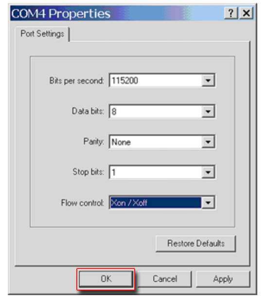
- A Properties dialog box will appear for the selected connection device.
- Use any of the drop-down menus to change the various port settings.
- Click OK once you have finished.
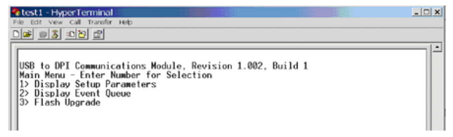
- After you click OK, you will get a blank screen.
Press Enter on your computer keyboard so the following test screen appears.
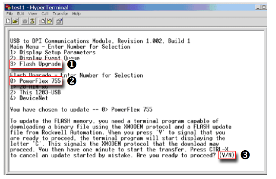
- From the Main Menu, select the flash upgrade (
 ) by pressing the number 3 key
on your computer keyboard.
) by pressing the number 3 key
on your computer keyboard. - Additional text appears. From the Flash Upgrade menu, select the PowerFlex 775
drive (
 ) by pressing the number 0 key on your computer keyboard.
 - Additional text appears. After reading the conditions, select Yes (
 ) to proceed by
pressing the letter Y key on your computer keyboard.
) to proceed by
pressing the letter Y key on your computer keyboard.
The terminal program will start displaying the letter “C”. This signals the XMODEM protocol that the download may proceed.
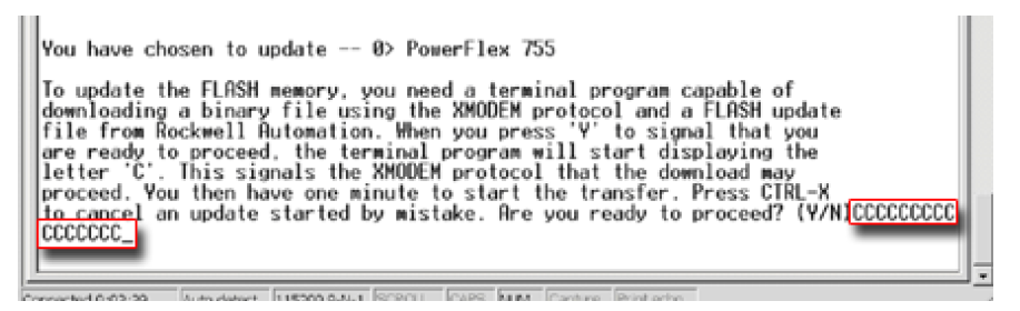
Important: You have one minute to complete steps 9…14 or HyperTerminal will return to step 5, where you must repeat steps 5…8.
Tip: To cancel the flash update at any time, press CTRL-X.
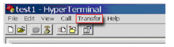
- Select Transfer > Send File to display the Send File dialog box.
- Click Browse and navigate to one of the following locations:
- For PowerFlex 755 drive frames 1…7, go to C: > Program Files >ControlFLASH > 0001 > 0086 > 0890
- For PowerFlex 755 drive frames 8 and larger, go to C: > Program Files > ControlFLASH > 0001 > 0086 > 0C90
- Search within the appropriate subfolder until the “PF755_LP_App_vxx_xxx_xxx.dpi” file appears in the Select File to Send list.
- With the file name highlighted, click Open so it appears in the Filename data field in the Send File dialog box.
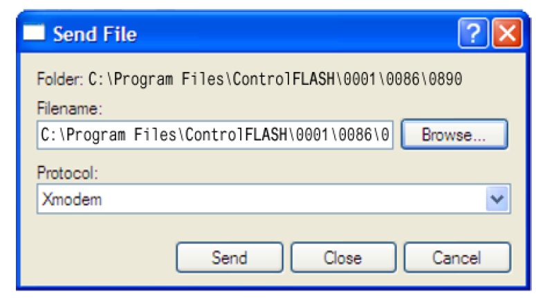
- In the Protocol box, select “Xmodem.”
- Click Send.
A dialog box appears and reports the update progress, which takes about one hour for HyperTerminal to complete. When it is complete, the message “Flash Complete” appears.
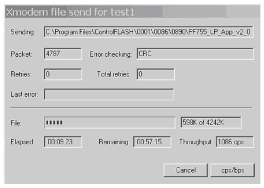
- Press any key to continue.
- Press the Enter key to return to the main menu.
Copyright © 2026 Rockwell Automation, Inc. All rights reserved.
Rockwell Automation, Allen-Bradley, and FactoryTalk are trademarks of Rockwell Automation, Inc.
To view a complete list of Rockwell Automation trademarks please click here.
Trademarks not belonging to Rockwell Automation are property of their respective companies.